|
| |
|
|
|
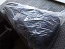
I bagged the whole instrument and case - you never know, rain, floods, volcanos...
|
Left: Once I had finished securing the bass inside the case I closed it all up and put everything in a plastic bag. Probably not necessary but no harm in playing it safe as possible! Right: Bass is now inside its shipping box with a lot more internal padded protection for added safety. FedEx has always done a great shipping job. |
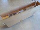
Everything is now safely inside the shipping box and I will go to great lengths to seal it up 100% for a safe journey.
|
|
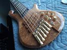
Everything seems to be working fine! I need to remember to take a bunch of glamor shots before I pack it up for shipping!.
|
Left: In the process of re-assembly and as soon as everything is back together I will re-test through an amp. All being well I can get it prepped for safe travel Right: I have a generous amount of padding and a box in which it will be safely packed. I'll be using padding inside the case and also inside the shipping box. |
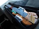
Ihis slightly blurry photo shows the bass in its case with a protective material between the strings and the fingerboard and padding to protect and prevent movement.
|
|
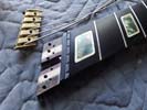
I could have chosen not to do this and it would have been OK but since I am cursed with being a perfectionist I decided to play it safe and do it!
|
Left: Stuff like this you never really know till the end of a build. In the process of stringing the bass up and testing I decided that the string retainer should be lowered maybe 1/16" just to guarantee a positive string angle. Right: Mission accomplished - lowered the joint surface just enough to be safe. Glad I have a CNC! |
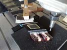
I re-machined the seat for the string retainer and now I will re-assemble and test everything.
|
|
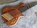
The bass looks and feels great. With the lighter set of strings requested by my customer the playing touch is light and sound is good. Rotary selector provides some great sounding pickup combinations!
|
Left: Strings back on the bass and I am now testing it for sound on the magnetic pickup department. Preamp and Pickup sound good in both active and passive. Right: Time for the final check on the electronics so I brought the bass to my trusted guru to make sure pickups were functioning correctly and grounding was good and stable. |

Bass is pretty much ready for my customer but I felt better having Mark take a final look at it and test the output and controls related to the magnetic pickups. Will go back and collect it tomorrow!
|
|
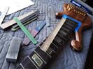
Moving along with the final dressing of frets and fingerboard surface and edges. Should have the strings back on soon for a final adjustment and test drive!!!
|
Left: I dressed the ends of all the frets and I'm now working on the final leveling of all the frets. Once that's done I will treat the fingerboard with more conditioner tofinish that part off. Right: Sealer/conditoner has been applied to the fingerboard and I am now waiting for that to dry. Maybe do another coat just for safety! |
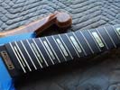
I applied a sealant and conditioner to the fingerboard surface. Takes a while to dry but looks great when applied!
|
|
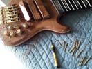
Got some good results on the adjustment screw modifications so getting ready to reassemble everything!!
|
Left: I finished the work on the pickup adjustment screws so I now need to put everything back together. They all sit much better in the pickup screw hole recesses! Right: Got the three pickups re-assembled back into the body of the bass with the refined adjustment screws. Everything looks good. Doing some final neck/fret cleanup now. |
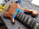
I got the three pickups re-installed in the bass and I will do the fine details of the height adjustment on each after the strings go back on.
|
|
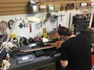
Went all the way back to see my electronics expert as I wanted to get the MIDI, piezo, pickup selectors and preamp tested.
|
Left: Went back with the bass to the Palm Springs area so that I could have my electronics guru do testing on the performance of the onboard electronic systems in the. Right: I took strings off so that I could un-mount the three pickups in order to better seat the heads of the twelve vertical adjustment screws. |
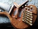 |
Working onthe details of the pickup covers and the heads of the adjustment screws so that I have the best possible combination.
|
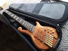
Test fitting the bass in its case - should workout perfectly!.
|
Left: Testing the instrument's fit in the Protec case. It's great that a headless bass can fit in a much more compact guitar case.Right: One of the finer details I want to get done is to refine the fit of the pickup height adjustment screw heads. They are special screws attached to threaded inserts. |
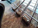 |
I want to refine the upper edges of the screw heads so that I get a better fit for each adjustment screw in the pickup covers.
|
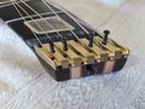
Lots of time going into this bass in its final stages to make sure it plays well and looks its best. Taking it tomorrow to the electronics guru to look at MIDIn.
|
Left: Working on a final polish and application of sealer on the fingerboard surface which will make it took clean, dark and beautiful. Also working on nut and nut slots. Right: Working on some of the final cosmetic details of what will be a beautiful and very unique instrument. I expect to be busy with fret leveling and bridge setup over the next day or two. |
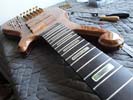
Doing some surface cleanup and finishing work on the fingerboard.
|
|
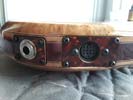
Glad to get the MIDI tested- running this over to my electronics guy to clean up what appears to be a minor switching issue.
|
Left: MIDI testing phase 1 has been done. I was able to get an assortment of sounds out through the 13-pin output which was great to hear. One small issue with switches which Mark tells me he can easily resolve. Right: Went to Fullerton today (between rush hour traffic) to pick up a Protec Contego case for the bass. |
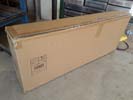
Just got home with the case for the instrument. I love these cases - they are lightweight and portable but still offer great protection for the instrument.
|
|
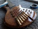
Doing some final wiring under the three selector switches and making sure the wires are tidied up!
|
Left: Doing a couple of final electrical connections plus will be polishing the top face and putting the gold knobs back onto the instrument. Nice looking bass! Right: The back of the instrument looks very classy with its covers on. I'm actually busy putting retaining magnets in each of them right now. Hope to MIDI test tomorrow! |
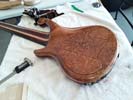
Making sure the covers fit and then I am adding the retaining magnets so that they can be left in place on the instrument.
|
|
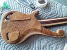
Covers are getting their individual retaining systems installed. Over the next 48 hours I will be having the eletronics checked at the shop of my electronics guru, and also picking up a case for this instrument!
|
Left: I am gluing retaining magnets into the three cavities to securely locate the lids on the back of the bass. Big day tomorrow - going to Palm Desert to have the entire electronic system checked. Right: Mark & I checked the pickup selector wiring and the preamp performance and those were good. Next test in the MIDI system. |
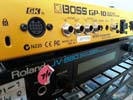
I am going to be testing the MIDI output using a Boss and Roland sound modules. Will update on results!
|
|
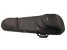
I will have to drive to Fullerton to get this case but it will be worth the trip!
|
Left: One of the really attractive features of a headless bass like this is that they fit in a GUITAR case which makes the instrument even more portable. Going to get one in the next day or two! Right: The gold locking strap attachments have been added to the front and back of the body - looking very elegant now that they are in place! |
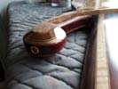
I have now installed the custom strap lock system into the front and back of the instrument body. As a headless instrument it will be very well balanced.
|
|
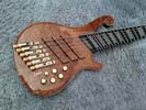
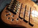
Bass is looking really nice. One of the few I have ever been able to make with matching front and back bookmatched grain.
|
Left: Wiring in the little circuit board, after which I will add some packing in the battery cavity area. Then I will test all the output systems and switching functions and do a major setup. Right: Busy getting the final wiring done and tidying everything up inside the control cavity. The PCB is getting installed and sealed in too. |
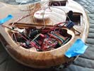
Getting what should be the last ofthe electronics done in this monster. Ready for testing and setup and I'm getting a case for it too!
|
|

Mark creatyed a custon PCB which I can add to the existing system to complete it all. Big relief and I will be getting that done asap!.
|
Left: Took the bass back to my electronics guy in La Quinta and he was kind enoughto manufacture a tiny circuit board to add to the LED circuit to complete the onboard system!!! Right: I am very endebted to my friend Mark for taking the time to create this little PCB board which now allows me to finish up the electonics in this bass!
|
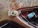
I am getting ready to seal up this little PCB and hook it up top the internal electronics.
|
|
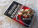
I will be installing this system on the bass -should work perfectly for a headless with a long upper horn!.
|
Left: Based on the profile of this bass the absolute best strap lock system is the Dunlop recessed design which is really discrete and provides a strong strap connection without visible strap buttons! Right: Marking out strap lock locations so that I can carefully create the installation holes and get the hardware mounted! |
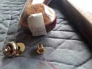
Iam marking out and drilling to mount the straplock hardware on the instrument.
|
|
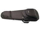
I am almost certain that due to this bass being headless, it will fit into one of my favorite GUITAR cases which will keep everything very compact and extremely portable for a bass.
|
Left: Got the small LED assembly installed and will be bringing the bass to my electronics guy for the final small electronic details! Also picking up a custom case for this instrument! Right: I'm experimenting with gold knobs to see which look best and also provide the best grip and access. The Glock has European size posts on pots. |
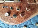
I had to find knobs that fit the non-us sized pots. All the gold harware will look really nice together!.
|
|
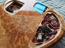
Almost done with all the back stuff.Willbe attaching the covers and adding some padding to the battery enclosures.
|
Left: Everything is coming together and I am almost finished in the control cavity. My electronics guy ordered a couple of special parts we need and I will bring the bass to him. Right: My setup on hardware is coming along. Action good and bridges are adjusted for intonation etc. Putting more conditioner on fingerboard. |
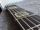
Working on nut, truss rod and bridge to get this instrument playing nice and comfortably.
|
|
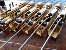
Working on bridge heights and intonation right now.
|
Left: Now busy with the actual setup of the instrument (neck, bridge, nut etc) to achieve a nice playing feel overall. Working out to be a very nice instrument! Right: I received the miniature LED units and I am now working that into the existing circuitry of the bass. This should complete all the internal work. Also working on bridge units. |
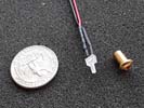
Using some cool technology for a discrete battery level indicator.
|
|
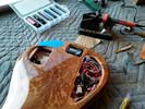
A little more bench work to re-locate one of the three batteries to the spare cavity!.
|
Left: I moved one of the battery connections (for the LEDs) to the now un-used cavity on the back of the bass. This leaves a much better space for the two batteries in the other cavity that power MIDI and Glock Right: Using some latest technology as I am adding a discrete extra small low battery power indicator to the system. |
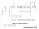
I have found it very helpful to have a indicator that will provide warning that the LED battery is nearing replacement.
|
|
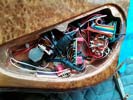
LEDs have been connected and set into the control cavity with everything else.
|
Left: I finally got the Glock, RMC MIDI, 3 pickup selector and LED light sources all into the control cavity, NOT an easy job but it's almost complete now! Right: You can never capture the impact of the LED powered side dots in a photograph but these came out really nice and a great option on this very classy bass guitar! |
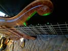
LED lighting is now operational so we're getting close to completing this monster!.
|
|
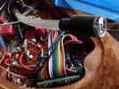
I have to create a connection between groups of fibers and the diameters of the required LEDs. Hardest part is just fitting everything between the existing electronics.
|
Left: Fibers are being cut to length and I am working diligently to heatshrink and flatten off and polish the combined ends of the groups of fibers. Right: I now have the leds set in lace and I am working on getting everything firmly attached together. Once that's done I will connect resistors and power supply to the lamps. |
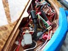
Fibers are cut to length and leveled and polished and I am now attaching the LED lamps.
|
|
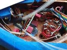
Fortunately fiber optic cables can be bent at least a little with the careful application of heat. I'll bend these cables round the Glock hardware and get the connections established.
|
Left: Separating the fiber optic cables and will be routing them to areas where there is space for the LEDs. At that point I'll prep the ends of the fibers and then connect the LEDs. Right: More work going on getting the fibers cut to the right length and also making sure the ends of the fibers are leveled and polished before bulbs go on. |

Fortunately fiber optic cables can be bent at least a little with the careful application of heat. I'll bend these cables round the Glock hardware and get the connections established.
|
|
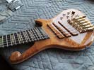
There's not a lot of space left in the control cavity for the fibers and LEDs after the Glock went in but I will work my way around all that!.
|
Left: This is a really nice looking bass - the wood grains are awesome. I'm separating the 12th and 24th fret fiber optics from the rest as I hope to make them a slightly different color. Right: My challenge is to get the fibers cut and positioned securely between the electronics and connected to probably three LEDs hooked to a power switch! |
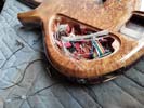
First step is to test with a small light to separate the four fibers going to the 12th and 24th fret positions from the rest of the fibers.
|
|

Working on getting over to Palm Springs area to pick up the re-wired bass. Asson as I hear back from my electronics guy I will head out there.
|
Left: Mark tells me he has re-designed and finished the electronics work on this bass and I now have to schedule a trip over to the desert to pick it up and get it back on my work bench! Right: As expected, Mark did a great job getting all these internal electronic features connected together. I will now be working on LEDs. |
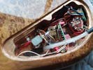
Got the bass back from Mark and it's now back on my workbench where I will install the LEDs and get the illuminated side dots working.
|
|
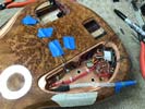
Glock preamp is now being connected to the rest of the electronics in the instrument.
|
Left: Rotary pickup selector back in now after having been reconfigured and rewired. This will now allow the installation of the Glock preamp to be done. Will have more progress photos very soon! Right: Glockenklang preamp is in the cavity and connected up. Mark is doing some testing now to make sure everything works together! |
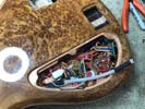
It was quite a lot of detective work to make sure Glock and RMC worked together. The units are being tested now so I should know more fairly soon!
|
|
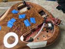
My electronics guru told me he's starting from zero because it will yield a cleaner job for the new preamp hardware. He'sbusy with that right now. I have the LED components ready for installation too.
|
Left: Bass is now in the capable hands of my electronics guru. He will connect everything related to the sound output and I will pick it up when done and get the physical stuff set up! Right: Mark is busy hooking up a complex set of electronics in this bass. I have been assembling all the LED items I need when I get the bass back! |

I am going to have to decide on a couple of colors for the side dots. I typically prefer blue or white for frets 12 and 24 and possibly amber for all the others.
|
|

Normally I consolidate several electronic tasks before driving to my friend's shop but in this case it really helps me to get the preamp etc finalized and get the bass back ready to make sound so I can do the final work.
|
Left: I have an opportunity to get this bass over to my electronics guru so that we can wire up and test the preamp and other electronics in this bass! Gonna do that first! Right: Decided it was safe to install the set of strings on the bass since we will be doing testing for sound and setting up neck, nut and bridge parameters. |
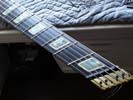
I wwanted the strings to be on while the bass was in the wiring shop. I'll do all the adjustment refinements when I have the instrument back in my hands.
|
|
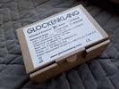
Glockenklang preamp has been safely delivered and I will get it unpacked and do some testing to see what I need to do to make it fit inside the control cavity alog with everyting else!
|
Left: Quite a big day for this bass - the Glockenklang preamp arrived and I will now be able to do some more work on getting it comfortably fitted into the existing control cavity. Right: Moment of truth as I try the Glock preamp components in the cavity. I will need to be careful of depth because of those circuit boards but otherwise OK. |
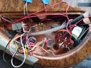
I was a bit worried about the spacing between the holes in the top plate but fortunately I can get all the Glock parts set inside the cavity - I will want to arrange them in the best possible way to provide space for the LEDs which I will be fitting on the fiber optics. I'll be busy but it looks do-able!!
|
|
I am making a small adjustment to the internal space in the control cavity as one of the Glock controls has a fairly significant circuit board attachment.
|
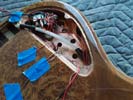
Left: I'm making a tiny bit more room on one side of the cavity for the circuit board of the Glock so that it avoids conflict with the fiber optic cables. Right: I have enough info on the Glock drawings I downloaded to anticipate where the various controls are going to be. With that in mind I machined the circuit board clearance. |
Based on sizes off of center of the pot on the drawings I machined a little clearance for the biggest Glock component. I hate machining aan already beautifully finished instrument body but I was extremely careful in this process!
|
|
Swapping preamp systems with somewhat different capabilites is challenging but it looks like the Glock that's coming in will work in the layout already eatablished in the control panel!!!.
|
Left: OK - good news - I have four holes in the control panel vacated by the Audere system, it looks like the four controls for the Glockenclang system will fit in the same spaces. Right: Having removed the Audere setup I went ahead and re-installed the rotary pickup selector control. May also set up fiber optic lighting. |
Swapping preamp systems with somewhat different capabilites is challenging but it looks like the Glock that's coming in will work in the layout already eatablished in the control panel!!!.
|
|
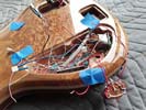
I'm thinking of at least uninstalling the Audere preamp so that I can plan for Glock component placement and getting the LEDs for the fiber optics connected up.
|
Left: Next move will be preparing the existing control cavity for the new preamp. I'm checking with my electronics guru to see if I should surgically remove the Audere. Right: I started on removing Audere which I need to do carefully. Noting the existing connections in case that is helpful when installing the Glock. |
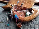
I'm now looking at the space I have to work with inside the cavity. I'll have to be able to get the LEDs installed on the ends of the fibers and also comfortably house the Glock preamp. In the meantime - staying busy!!!.
|
|
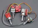
Even in the non-covid world this particular Glock combo is hard to get since it's a less common build, especially with the 3-band option. I have been told there is one available but very hard to communicate directly right now.We should be OK from what I have learned.
|
Left: I have both called and messaged with GK and their distributors (those I can get hold of) and it looks like I can get one with 3-band EQ. Lucky, as it appears, they actually have one in stock. Right: Glockenklang custom 1-pickup 3-band preamp has been officially ordered and is on its way. Need to get Audere out of there! |

After a lot of searching and background work the specific Glockenklang preamp we need it ordered and on its way.
|
|
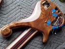
The 1 pickup Glock configuration might be a solution for us - I will know more soon regarding the electronic compatibility and related challenges but it would be great to have a solution!!
|
Left: Measuring the cavity space for possible Glockenklang replacement. If that works out to be the case I will remove the Audere and will work with my electronics expert to get all this working! Right: My electronics guru and I agree that this 1-pickup Glock would work with everything else - I am trying to see if I can get one in USA. |
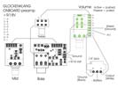
From all the info I can gather this is the layout of the 1 pickup, 3-band Glock preamp that would work with the existing system and fit in the available space. If not it would be close in size and I am sure I could at least slightly modify the cavity!
|
|
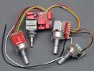
This is the Glockenklang 3-band active/passive system. Seems like the best candidate if I can find a way to get it to fit inside the bass and add another potentiometer hole for the extra control!!!
|
Left: Current Audere is a 3-stacked knob system. Smallest Glock I can find for 3-band has 4 pots. I'm currently working on seeing if this will be feasible in the existing physical cavity space! Right: Glockenklang informed me of a unit that I had not previously run across - a 1-pickup model of their A/P preamp that MAY work with this bass. |
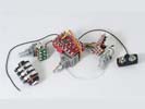
I believe it is still a 3 band control unit. Since we are routing the 3 pickups through a rotary selector switch it seems that that output would work with this preamp - I'm asking a lot of questions right now to my suppliers and my electronics guy!
|
|
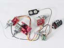
I'm looking at trying to get a 3-band Glockenklang that will fit in the control cavity area of the bass.
|
Left: I'm looking at getting the electronics on this complicated instrument finished up. I have one client interested in a Glockenklang preamp so investigating that! Right: My ONLY worry with this bass is that I only have so much interior cavity space. Adding the larger Glock may force me to trade that for existing MIDI or LED features. |
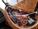
Right now I have a custom Audere preamp, an RMC MIDI setup, a rtary control to manage the 3-pickup system and a set of fiber optic cables that need to be connected to LEDs. Not much space left in there!
|
|
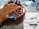
I have done a very careful job of wiring the small switch. These small switches are sensitive to too much heat so I want to test it before installing just to be sure soldering didn't compromise anything..
|
Left: I have the phase switch temporarily wired up so that I can test its function before permanently installing it in the control cavity. If all is ok I will shorten and reconnect wiring and install it in place. Right: Working on the bridge units to dial those in close to working height and for optimum pitch. Hoping to have this all finished soon! |
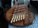
Getting the bridge units set up and I'm hoping to have it strung up and making noise soon.
|
|
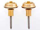
These are some of the best strap buttons available. Easy to attach and look good on the instrument itself.
|
Left: I will be installing Dunlop locking strap buttons on the bass. I'm using the recessed ones since we have a slightly narrower upper bout and this will work best given the shape of the instrument. Right: I drilled the body and recessed the inside of cavity to accept the switch body. The pre-wired switch fits next to the selector switch. |
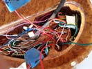
I added the two remaining wires to the tiny terminals of the switch and fitted it successfully next to the rotary selector switch. Now I just have to hook up the four connecting wires.
|
|
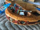
Output jack now in and selector switch re-installed. Next task is to wire up the phase switch.
|
Left: OK - got that done - I had to remove the selector switch to get the output jack fitted. Jack now in and secure, plus the selector switch has been re-installed. Moving on... Right: This is the extra-small phase switch I will use due to tight spacing inside the cavity. That wiring was hard to do because it was so small!!! |
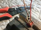
I opted for wiring this mini-switch outside the cavity and then installing and connecting the wires. It would have been much harder to do this insider the cavity space.
|
|
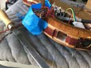
I'm filing the sides and corners of the jack socket to allow the slightly larger than planned output socket to fit in the side of the bass.
|
Left: Because we had to purchase a more advanced output jack socket with additional terminals, I have to slightly enlarge the through hole in the side of the body so that I can permanently fit it. Right: Up early and worked on the socket so that I could get the jack assembly to fit into the side of the body. Got that done! |
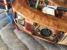
I will attach this output plug to the body using a small plate similar to the MIDI output shown in the photo.
|
|
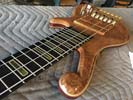
Feels good to have the electronics of the instrument resolved, I am now working on numerous tasks to get things closer to completion.
|
Left: I have locking strap buttons to add, a new set of strings, several gold knobs, I will be cleaning up the neck and adding conditioner to the ebony, some pickup height adjustment and more! Right: This is the net control layout except for one small phase switch which I am about to install. I'll post a photo with the knob/switch functions. |
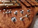
Adding the phase switch gives the 6-position pickup selector 12 different sounds.
|
|
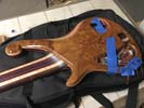
Very good bews in that I now have the bass back in my care. Mark and I spent a good part of the afternoon discussing the final electronic details and we are moving forward!
|
Left: Just drove two and a half hours each way to evaluate the bass with my electronics guy and decide on the final details. We felt confident enough to send the bass home with me! Right: Mark set up the wiring to inlcude a phase switch for the center pickup so that we can not only potimize the output but get more sound options! |
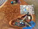
I'm going to discretely install this gold switch to provide phase selection which creates a second set ouf sounds for the bass. I will also be fitting the new output socket we had to get.
|
|
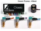
The comination on this preamp frees up one position on the control panel so that we can add a blend pot.
|
Left: OK - we are switching out the Audere 1 for the Audere 2 setup in order to allow all features of MIDI control and preamp to work in harmony. Last phase as all the techies agree on the wiring scenario!!!! Right: Mark now has installed the replacement preamp and everything is connected per our plans. Testing it all tomorrow. |

I'm going to discretely install this gold switch to provide phase selection which creates a second set ouf sounds for the bass. I will also be fitting the new output socket we had to get.
|
|
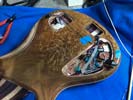
Adding a dual potr would allow the unassigned wiring to be put to use and provide more options for teh player. As far as I understand we are fixing a problem by adding a new feature which is good.
|
Left: Latest news is that we may swap out a single potentiometer for a dual pot so that we can have both synth volume and magnetic signal blend. I'm waiting on more info on this. Right: From numerous communications between us, RMC and Audere this is the configuration we all agreed on. I feel relieved.... |
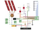
This is a simplifed version of the revised drawing we all feel conficent will provide all the electronic features. I have to swap the Audere out for another Audere with an extra blend pot for it all to work!!!.
|
|
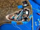
I don't completely understand the intricacies of the wiring but my electronics guy was able to send me updates showing the RMC unit and the rotary pickup selector have been wired tp piezos and pickups respectively.
|
Left: The RMC unit and the multi-position selector have been installed and the wiring has been established between the pickups and the selector switch. MIDI output also in place. Right: The Audere 4 band preamp has been fitted and almost wired in to the other electronic packages. I spoke to my guy and he tells me it's almost there. |
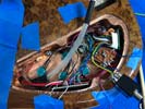
Mark has the equipment to create quality soldered joints and electronically test the results. A lot of the work we have had to do has been finding ways to connect everything together and retain the functions we want on the instrument. Some of this work has involved out having to communicate with the preamp and MIDI processor manufacturers for technical specs. All above my head but I am glad we are almost there. We have narrowed everything down to the assignment of TWO remaining wires. Checking with manufacturers.
|
|
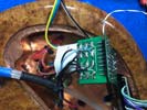
The RMC processor is remarkably small considering all it does. It has a huge amout of wires in and out of the unit though.
|
Left: This photo shows the RMC MIDI unit with the six piezo wires connected to its circuit board. We now have an output for the MIDI signal. More info as I get it. Right: The new multi-pin jack socket is being wired into the system to give us standard output to a 1/4" jack. It was necessary to a socket assembly like this one. |
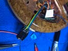
Some of the RMC wiring and some of the Audere preamp wiring plus power connections all have to go to the output jack to make this work correctly! .
|
|

We now have the Audere preamp which we know is compatible with the RMC MIDI system. We'll be working to get it all hooked up internally.
|
Left: We received the Audere preamp which was configured to work with the established control layout. We will now get this system installed and hooked up to the other electronics on the bass. Right: Audere 4-band preamp is being installed. Mark also ordered special output jack to allow everything to communicate internally. |
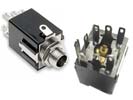
Pickup selector is set up, Audere preamp is fitted and being wired. We also ordered multi pin output jack to allow the various feeds and switching to operate correctly.
|
|
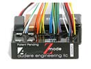
It has been a lot of work to get to a place where our preamp, piezo input, MIDI conversion and magnetic pickup output and processing all work happily together. I think we are just about there.
|
Left: I'm having my electronics guy finish the wiring in such a way that the magnetic pickups, RMC MIDI and Preamp all live happily together. That way I can finish the remaining work on the instrument. Right: It turned out that the MIDI system and the Richter preamp were not electronically compatible. We will have to use a different preamp. |

We are ALL working to seek the best electronic solution.
|
|
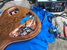
We are working on the task of having the MIDI system and preamp components talk to each other. We have been in touch with component manufacturers for their work-arounds. This all goes way deeper than my basic knowledge of electronics but I know they will work it out.
|
Left: Something I didn't know and my electronics guy informed me - the piezo mixer board requires its own power supply. With the RMC midi, 3 pickups, Richter AND the LEDs I may not be able to incorporate that board due to lack of available space and power supply! Right: My electronics guy is finishing up the internal wiring! More info soon!!! |
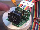
This is the output boqrd of the RMC Poly Drive which balances piezo input and converts to a selectable MIDI signal.
|
|
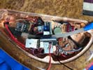
WThe three pickups have been wired through to the rotary selector switch. Right now we are trying to get the piezo signal to talk to the RMC MIDI components. My electronics guy says this one is pretty demanding in terms of making signals communicate the way we would like then to.
|
Left: Some of the wiring from the pickups through the multi-position selector switch has been done. We are working on the Richter and RMC requirements to resolve power supply demands right now. Right: Moving ahead with the wiring scenario - we have a limit of three 9v batteries and are trying to make everything work on that basis!!!! |

WThe three pickups have been wired through to the rotary selector switch. Right now we are trying to get the piezo signal to talk to the RMC MIDI components. My electronics guy says this one is pretty demanding in terms of making signals communicate the way we would like then to.
|
|
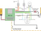
This is part of the RMC wiring that he is working on - I'm hoping to get a couple of photos of the bass on his bench and I will be going to pick up the finished wired instrument very soon!.
|
Left: We are busy getting the internal wiring hooked up. Some of it realted to the pickup selections is quite complicated but the bass will be almost done once that's completed. Right: We are being careful to leave space between the electronic components for the cluster of fiber optics. These will be connected to LEDs. |
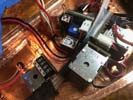
Working around the fibers which I will eventually trim and connect after all the wiring is safely completed.
|
|
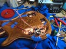
This photo is from my electronics partner's workbench where he is wiring up this monster. Ititially he is cutting and connecting all the piezo wires from the bridge units to the little Richter mixing board in the new recess. He will test all these output signals and send the output from that board through to the blend pot. Glad he is doing this and not me!.
|
Left: My electronics partner is currently working on getting all the fairly complicated wiring established in this bass. Hardest part is probably the multi-pickup selector. Right: This is the new cover I made for the piezo cavity I just recently machined. My finisher was kind enough to apply poly-resin coating to it so it would match the bass body. |
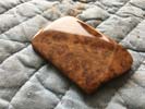
My finisher did an awesome job getting this little piece processed through finishing for me.
|
|
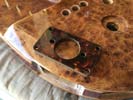
A little upgrade because I had the material - rather than normal black plastic plates I am making plates from a material that matches the wood.
|
Left: I wanted to show this image which is the material I am using to create the custom plug mounting plates. Nice match with the natural wood grain. Right: Spent some time getting the RMC MIDI output board located in place and secured into its recess on the side of the body. Great to get this fairly complicated component set in place. |
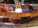
The MIDI output socket is now set in place. I put gold screws in there but I think it would look more discrete withg black screws - we will see.
|
|
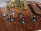
This is what the bass looks like with all its controls set in place. Glad this is all done - it was a lot of work.
|
Left: The bass now has all its controls, switches, hardware and wiring set into the body and I'm doing some final testing so that I can bring it back to my electronics guy. Right: Bass is now headed back to the desert where my electronics guru will finish up the required connections and make this instrument able to talk! |
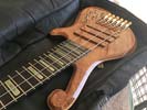
Only need 3 strings to adequately test for sound and I don't want to spoil a new set (which I will put on when all is complete).
|
|
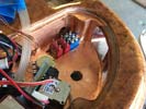
One more tricky little task out of the way - I can now fit all the hardware into the instrument!!.
|
Left: just wanted to show a photo of the three switches that now will live in this corner of the control cavity. One is for the LEDs, the two red ones relate to the RMC MIDI functions. Right: It was a demanding job to run 3 sets of power wires through to the battery compartment. One for LEDs, one for Richter and one for RMC. |
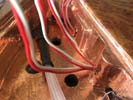
We had to work for a white to get six power wires through from the battery recess to the control cavity.
|
|
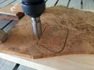
Cutting out the new cover for the little recess for the Richter piezo card. I'll have it gloss finished to match the rest of the instrument and it will look awesome.
|
Left: Getting this cover cut out as quickly as possible so that I can get it nicely fitted in the new recess that was machined. I was careful about matching grain. Right: I established a hole connecting the piezo board cavity to the main control cavity so this work is now done. The cover is going to my finisher while we finish up wiring. |
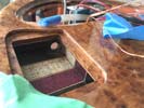
Carefully drilled a connecting hole for the piezo wiring in and out.
|
|
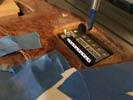
So far so good - all going well. I'm going to make it just deep enough to clear the mechanical connections on the board.
|
Left: The second phase of the cut is to create a recess deep enough to house the board and also allowing enough lateral space for the incoming/outgoing wiring. Right: End result of the machining gave us a nice area in which the Richter board can live. I will now cut the matching lid and get that gloss coated so that it is a beautiful blend. |
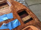
I gave the recess a coat of sealer to stabilize the bare wood. I will cut a lid and get that fitted and finished. Now back to the remaining work on the electronics!.
|
|
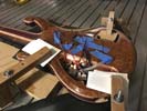
I was going to locate this pocket per my last photo but I didn't want the piezo wiring and the related output to have to cross the entire control cavity if it didn't have to. There is just enough space at the back end to add the same feature. Very busy as I want to get this done and back to final wirng.
|
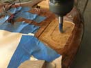
Left: The bass is going to get a little recess and cover created for the Richter circuit board. After a LOT of research I'm putting it at the back closer to the piezo input wiring! Right: This has to be one of the most delicate and careful machining operations I have done, right now removing enough surface material for the cover plate. |
I will cut a very closely matching piece of the same material and have it finished to match this cover area really well. Right now the challenge is to machine it and avoid chipping the surface finish.
|
|
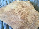
This is why I always keep the offcuts of the wood I use on instruments. THis is the same piece from which the back material was cut and I will match the grain before cutting the cover.
|
Left: Fortunately I have some of the parent wood I can machine and take to my finisher to create a beautifully matched cover so that the extra Richter cavity will be just one more elegant feature on the back of the bass! Right: This is the area (yellow) under which I will create a small recess to house the Richter Piezo mixing board. |
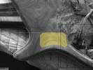
Fortunately I have a ver good matching piece of Amboyna Burl that will work very wel in this area.
|
|

Having the strings attached lets us test both the piezo signals and the magnetic signals.
|
Left: The RMC MIDI ststem required two mini toggle switches and I needed another for the switching function of the LEDs. There's a LOT of stuff to fit into this control cavity! Right: After a few tries we decided that the Richter Piezo board is just too big to incorporate with all the other electronic parts. I will make a new cavity/lid for this part. |
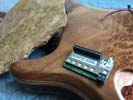
The only way we can incorporate this Richter feature is to cut a recess for the board to cooupy and create a carefully matched amboyna cover which I will have my finisher prepare to perfectly match the area.
|
|

Having the strings attached lets us test both the piezo signals and the magnetic signals.
|
Left: While the bass is at the electronics workshop I do have a few photos I havent posted of work done - in this photo I was establishing and drilling the holes for the strap hardware. Right: The electronics work should be completed soon and after I get the instrument back I will be doing a complete setup to bring everything into playing condition. |
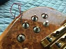
This photo was taken just after I established locations for each of the electronic components but before I added the two holed for mini toggle switches.
|
|
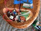
The connection of all the electronic hardware si a little tricky but my electronics partner says it will be no problem! Piezos, MIDI, and lots of pickup selections.
|
Left: Bolting in the electronic components to the control cavity so that wiring can get started. Just trying to ensure that everything is arranged and spaced so that there will not be any phyiscal conflicts! Right: The bass is now going off to my electronics expert to connect all these electronic compenents together and make some sound!! |

I am very lucky to have an electronics guru within a couple of hours drive who understands complicated MIDI systens like this one!!!.
|
|
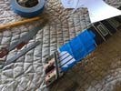
I'm cutting string slots in the nut so that we have some strings on the instrument when testing the pickup and MIDI signals.
|
Left: Right now I am cutting the string slots into the nut using a llittle template I printed from a vector program. Once the slots are deep anough I will reassemble and add strings. Right: String retainer back on and I am adding strings so that we can test for sound throughout the process of connecting up all the electronics. |
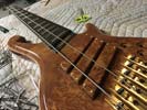
Having the strings attached lets us test both the piezo signals and the magnetic signals.
|
|
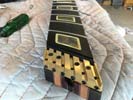
Very high tech string retainer now fixed to the neck - I'm adding the nut also and we will be ready for wiring.
|
Left: The string retainer is now part of the neck assembly and I am cleaning up a nut to insert in the nut slot. Once that is done I will string the bass up. Right: We are very close now to taking this instrument to my electronics expert who will hook up all the selectors and MIDI components and switchs and make it talk. |
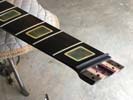
Getting the nut blank established n the neck.
|
|
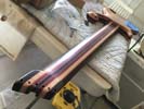
IAdding soem nice decorative sleeves to finish the back of the headstock.
|
Left: I'm working on the back of the headstock where I will be installing gold plated sleeves in the holes for the strings. Once these are in I can get some strings on this bass so we can wire it up! Right: Holes drilled out and I inserted the sleeves to finish the area off. I will now attach the string retainer and nut so that we can get strings on! |
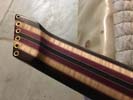
These sleeves are a nice way to finish off the back of the headstock.
|
|
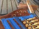
These counterbores take care of all the controls except for the RMC Midi control. I will probably use a smaller knob for that pot so it won't need a counterbore. If it does I will just repeat this operation for that control knob position.
|
Left: Cutting the recesses on the top for the knobs went well. I have machined all I need to for the moment and I will now seal the bare wood so that everything is safely protected. Right: Bass is off the CNC and I am now adding a sealer to protect both the finish and the bare wood. I can now get the electronics installed for wiring. |
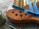
I'm sealing the exposed wood fron the counterbores into which the knobs will fit.
|
|
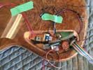
When you consider there will be LED connections and the Richter piezo curcuit board I have to be very careful that everything goes in comfortably. The circuit board will go in top right abiove the RMC midi control. Phew!.
|
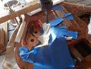
Left: After spending time comparing locations for internal hardware I think we will distribute them this way. I need space for the fiber optics and this should provide that. Right: Instrument is being very carefully set up on the CNC so that I can cut relief counterbores in all the existing holes so that I can install hardware. |
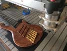
The rlief allows space for the locking washer to grip over the potentiometer threads and also keep from having too much space between the top of the bass and the bottom of the knobs.
|
|
|
|

