|

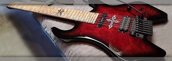
On the bench for some close to final adjustments. My customer wants tohave it and so some of the very final adjustments since he is very familiar with workking on guitars. Will be driving it there to deliver!
|
|
|
|

On the bench for some close to final adjustments. My customer wants tohave it and so some of the very final adjustments since he is very familiar with workking on guitars. Will be driving it there to deliver!
|
Left: I'm now working on the tension on the tremolo unit springs, and setting the bridge adjustments so that we get closer to a comfortable playing setup. Some nut slot work too. Right: I cut a couple of carefully sized pieces to fill the heel of the neck so that I can use all of the colored material in the visible part of the neck. |

On the bench for some close to final adjustments. My customer wants tohave it and so some of the very final adjustments since he is very familiar with workking on guitars. Will be driving it there to deliver!
|
|

Busy with all the wiring - just the pickups to connect now. Will tidy up wiring inside after I test everything.
|
Left: All the grounds have been attached, selector wired, I just have to connect the two wires from each pickup to complete the wiring per my diagram. Right: I installed a set of strings on the guitar so that would be able to do several tasks. One is to test for sound, but also to adjust tremolo spring block and work on nut and frets. |

Put a set of strings on the guitar so that I can do all the remaining adjustments.
|
|

Wiring gettig connected in the control cavity. Output plug assembly installed.
|
Left: The output plug assembly has been wired up and installed into the side recess of the guitar. They need to be connected to the internal grounding and the volume pot. Right: Getting the 3 way switch wired up and connecting the volume pot and all the grounds. If my drawing is correct we should get sound!! |

Getting through the wiring in the cavity - almost there.
|
|

Marking out and drilling holes for the tremolo spring cavity cover.
|
Left: I'm getting the holes drilled into the back (spring cover) plate so that I can attach it to the instrument and consider that component done. Right: Logo art fixed into the top of the guitar. Now going back into cavity to clean up wiring and if all of that works out I will put strings on a test output and switching to make sure that's OK. |

The artwork between the pickups has been attached.
|
|

Magnets in covers and shielding on the control cavity inner surface.
|
Left: I established the locations of the magnets on the back of the two covers and drilled and installed magnets to match those in the recess in the body. Also lined the cavity cover with copper shielding. Right: Getting all the various pieces assembles to create a complete guitar. Almost done with wiring. Securing logo piece in top. |

I'm adding knobs, strap buttons and the logo between the pickups right now - very busy!.
|
|

Using metal shims to make sure magnets set in the glue flush with the top surfaces.
|
Left: Magnets in for both covers and I am getting the pickup wiring done right now so that I can get some sound out of this instrument! Also adding magnets to inside of both covers. Right: Just got the rest of the copper shielding installed over the magnets in the control cavity. Now moving on to the actual wiring inside. |

Got the remainder of the copper shielding into the control cavity.
|
|

Time to get the pickups wired through the selector switch to the output socket.
|
Left: As far as I can tell this diagram I created correctly defines the wiring from the pickups through the selector switch to the output socket. Right: Working on the fitting of the two covers and getting the magnets installed. I'm also working on the wiring of the pickups as they relate to the internal switches and potentiometer. |

Getting the back cover plates fitted and set.
|
|

Ground wire in connecting hardware (and strings) to common ground.
|
Left: Got the grounding wire from the tremolo assembly harware run through to the common ground in the control cavity. Not easy to get a good joint on that bracket but with enough heat it worked. Right: Wiring is being arranged and I've reinforced connections on the two LEDs and secured them together in the cavity. |

Securing some of the internal wiring and components so they don't move.
|
|

Cut a custom cover for the back.
|
Left: I cut a spring cavity cover and the material is the perfect thickness and color and it looks great. I'll establosh retaining screw holes and break the outer edges and this will be a great looking cover. Right: I'm installing the output jack in the side of the body and this will allow the rest of the wiring to be completed. Looking good. |

Jack socket now in place and I'll be finishing up the wiring.
|
|

Ongoing cavity work - most of it done though.
|
Left: Got LEDs connected and now working on getting the lids ready to be attached to the body. Installing magnets and when those are in will add the rest of the copper shielding. Right: Difficult to adequately show the side lights on the fingerboard using a phone but they look really good. All red except F12 and F24 in white. |

Side lights on fingerboard activated.
|
|

Installing the volume pot and have the second LED connected it fiber optics.
|
Left: Installing second LED for the fingerboard illumination. I'll test the two way switch on this and secure both switches in the body if everything is working. Right: Drilling some holes for installation of neo magnets that will be inserted to retain the control and battery covers onto the back of the instrument. |

Wiring being attached to the LED lamps. These connections are delicate but I will reinforce them.
|
|

Got one of the two bundles of fiber optics connected to their LED lamp.
|
Left: Working on the connections from Fiber Optics to LED bulbs. It's always a bit tricky as everything is a different diameter and needs to be securely connected together. Got the smaller bundle done already. Right: Working on the second LED connection plus I get the pickup slector installed so that it can be wired up! |

Pushing as hard as I can to get all this stuff finished and complete the instrument.
|
|

Logo light are now hooked up througn one of the mini toggle switches.
|
Left: Testing the lights for the Logo area of the instrument. I now need to fit the cover panel with the aretwork and this portion of the work is done. Right: Working on shortening and preparing the ends of the fiber optic cables so that I can connect them to LEDs. This is tricky work so I am being very careful. |

Identifying each fiber optic and I will be assigning dot colors.
|
|

Switches are in and ready to be wired up.
|
Left: The relief cut for the switches worked out well and I can now lock the switch units in place. I will now go ahead and connect up the power supply wires to these terminals. Right: I'm wiring in the two switches to their power sources and also connecting power through to the logo LEDs. The neck LEDs will follow that. |

One off switches for LED power being connected up.
|
|

Holes for switches have been established. Now I need to do a quicj machining op on the inside!
|
Left: Got the two holes drilled for the two black switches. I will need to do a little machining on the inside of the cavity to extend the threaded shafts through to the front. Right: It was necessary to relieve the base surface inside the cavity for the two switches so that I will have enough thread on the front side to lock switches in place. |

Machining some relief to fit teh switches.
|
|

A switch for each function is easier and more flexible. These blck switches are small and discrete.
|
Left: In order to provide independent switching for the logo and the fingerboard lighting I am adding two small independednt on-off switches. Right: Getting the selector switches located in the control cavity so that I can drill the holes and get them installed. They will live in approximately this location in the cavity. |

Installing the two lighting switches in the control cavity.
|
|

Getting the lights installed in the guitar body.
|
Left: The frame of LEDs lights is now in the recess and I will get that secured. I'm also adding little black screws to retain the two pickup surrounds. Right: Got the two pickups secured in with their little screws and I'm checking thefit of the logo to make sure everything will fit correctly in place. Back to wiring and LED power. |

Some more work on the pickups and the logo cover piece.
|
|

Got things working the way I wanted and I'm now going to get that center logo illuminated.
|
Left: Got the framework of the logo LEDs together - two sets of three lights worked best. I will seal and trim this and install it in the little cavity. Right: OK I got the little set of 6 leds set and wired together and ready to install into the logo cavity. Once they are set inside and wires are run I'll fix in place and attach logo. |

Running two pwer feeds to 6 LEDs through on resistor.
|
|

Getting some if the electronic hardware installed into the cavity.
|
Left: Pickup selector and volume control are being fitted and installed. I have also permanently installed the two pickups. I'm now doing some of the asic wiring before moving to LEDs Right: Working on wiring up the LEDs in such a way that they will work correctly with my resistor values. Looks like two sets of three works. |

I have two 9v batteries sending power in parallel. Need to set up LED resistors so that everything is balanced properly.
|
|

On a race to the finish line here - gettig all the wiring established. Should be awesome!.
|
Left: I have strings here which I am going to install on the guitar. Also getting all the LEDs and related connections together. Busy time - more pictures coming! Right: I am working on getting the LEDs lighting set inside the instrument so that this logo can light up at the flick of a switch (or push of a button). Should look great! |

Will soon be adding light to this logi between the pickups.
|
|

Cutting a recess for the pickup switch.
|
Left: Doing a quick CNC operation to machine a little clearance for the 3-way switch so that it clears the cover and that the switch operates fully end to end. Right: The guitar is on the electronics bench and I am soldering some of the common grounding wires and battery connections. Also ready to wire up the 3-way selector switch. |

This photo shows the connectors to the twop 9v batteries for the power to the LEDs.
|
|

Tremolo mechanism is now installed. Will do foional adjustment after strings are on.
|
Left: I had to buy some drills and extenders to give me access to these holes so that I could drill them at the correct angle. It all worked out and the installation is done. Right: I'm currently working on all the internal electronics so that I can get sound and light out of the instrument. Will have more photos of this very soon! |

Working on internal electronics.
|
|

Running power cable through from battery cavity, behind tremolo (through aluminum tubing) and into control cavity for lighting.
|
Left: Working on the internal features of the guitar. I'm running power supply and grounding wiring through from battery compartment to control cavity. Right: Drilling holes for retaining screws and will have to decide how much tension is ideal for this bridge. I can add springs if I need to but I think these three will work fine! |

Carefully setting the screw locations and angles so that I can get the retainer and springs working.
|
|

Modified bridge has now been fully re-assembled.
|
Left: I'm now re-assembling the tremolo bridge so thatI can get it installed in place on the guitar. Block is attached to the bridge and I now have to fix it onto the body. Right: The bridge went onto the body recess nicely and I can now assemble some of the spring assembly parts in the back cavity so I can test it. |

Modified bridge back on the instrument and it's looking good.
|
|

Taking a little off the tremolo block so that the assembly will be flush with the back of the guitar.
|
Left: Doing a little machining to the overall height of the tremolo block so that the tremelo assembly matches the thickness of the body. Right: Got the tremolo block resized to fit the recess on the back of the guitar leaving enough space for the tops of the springs. I can now re-assemble the parts and install the tension springs. |

A little extra work getting the tremolo parts to work but that's done now - moving on!.
|
|

Getting dug into the internal wiring so that we have sound and then lighting wired up
|
Left: Have the grounding wires threaded through to the control cavity and I'm readt y tro get the rest of the internal controls installed so we can get sound out of this beast. Right: I'm finishing up the copper shielding in one of the pickup recesses and establishing a grounding wire to the shielding that runs to the control cavity. |

Doing some copper shielding and grounding so that I can bolt in the neck pickup.
|
|

Wiring for bridge grounding next then power wiring from battery compartment.
|
Left: Now that the birdge is in and working I need to get the grounding wires and the electrcal power threaded through to the control cavity area. Right: Looking at the base block of the tremolo unit so that I can slightly modify it to work with the body thickness of this guitar. Some minor machining necessary to make it fit. |

I need to remove wome material from the length of the tremolo base block to match the thickness of the guitar body.
|
|

Neutrik jack socket fitted and now looking at wiring in the control cavity..
|
Left: I got the Neutrik jack socker fitted into the body after some grinding to remove overspray. I'll get thos screwed in place and move on to the installation of the electronics. Right: Adjustments made successfully on bridge - now I need to establish the actual fit and size for the spring block under the tremolo bringe. |
Neutrik jack socket fitted and now looking at wiring in the control cavity..
|
|

Just about ready to install the bridge which will allow me to get some strings on this instrument!.
|
Left: The guitar had to go up on the CNC to get the pickup recess lowered slightly but everything now seems to have settled in place. I have to cut the little recess for the handle slightly deeper. Right: I installed the bridge assembly into the guitar. Good to get this on and get a feel for how everything fits. |

Bridge fits in well but I may want to give it a tiny bit more clearance at the back tp give it clear tremolo travel. Feel it binding just a tiny bit..
|
|

Working on both the nut and the string guide.
|
Left: I am adding strings to the assembly mainly to check and see how the nut, neck and bridge all align relative to each other. Right: All good on string alingnment relative to neck, bridge and pickups. Bridge is still a little higher that I would like so I may machine the seat for the bridge a few thousandths deeper to optimize that. |

Working on both the nut and the string guide.
|
|

The template I attached to the fingerboard helps me cut the nut slots in just the right positions!!.
|
Left: I have a template for helping me position the nut slots accurately based on the nut width. This will allow me to get strings on this guitar so thatr I can do some of the final testing. Right: Slots being cut into the nut and I'm also plotting screw positions for a carbon fiber insert which will support the strings in front of the nut. |

Working on both the nut and the string guide.
|
|

Tremolo seems to work correctly in the new recess. I will have top set iut up with strings to truly test its function.
|
Left: Testing the bridge assembly in the new recess. I want to make sure it has the required movement for the tremolo. I will also have to slightly shorten the spring block to match the body thickness. Right: I will be putting strings on this instrument soon so I need to finish up the mods on the tremolo block and assemble everything! |
Tremolo seems to work correctly in the new recess. I will have top set iut up with strings to truly test its function.
|
|

The two blocks that hold the pins for the tremolo action need to be cut a little deeper than the rest of the bridge I'm being careful with all of this so we end up with a good freedom of movement at the right height.
|
Left: Had to dis-assemble the tremolo unit to make testing of the bridge unit possible. I will make a couple of minor modifications to the block once I do the final install. Right: Bridge unit is in place and appeard to have all the necessary movement for the tremolo. I will get everything assembled for a test and see how it works! |

As far as I can tell the machining is complete and it looks like everything will work mechanically.
|
|

I will be machining a small rectangular pocket to allow bridge and tremolo to work.
|
Left: Getting ready to machine an area below the bridge to create a solid pocket for the bridge assembly and allow optimum alignment with the strings and neck. Right: Instrument is under surgery to get the bridge set into the instrument. I need to test for the tremolo movement once the depth has been achieved. |

I was able to get the profile of the bridge machined into the exact area of the top based on the scale length of the guitar..
|
|

Working on getting the nut installed and the string slots cut into it.
|
Left: I am installing a nut into the nut slot so that I can get the set of strings onto the instrument. After that it's just a case of setup and testing. Right: I am adding a carbon based block at the end of the neck to provide a low friction radius to allow the trings to pass from the retainers to the nut without a sharp edge. |

This block will be cut to size and probably attached with a couple of very small screws between strings.
|
|

Both pickups fitted into their recesses.
|
Left: I spent time with a small dremel bit getting overspray out of the logo recess so that the logo would fit in there better. It's now well seated and I will secure it in when the LEDs are set. Right: Based on the height of the bridge and the body/neck angle I will probably nest the tremolo unit into the body slightly. Working on a program. |

I want to nest the bridge a tiny bit lower in the body so that everything lines up correctly.
|
|

Pickups looking good in their fancy red surrounds. Now I have to get them set into the guitar body.
|
Left: I got both the pickups set up in their own pickup surrounds so that the heaight adjustment is functional. Now I will install them in the body of the guitar. Right: I had to do a little modification to the very long screws for the humbucker pickup but now it's all set to be installed permanently along with the neck pickup. |

Both pickups fitted into their recesses.
|
|

Neck pickup ring which I made from red trans material!.
|
Left: I decided to take the red one step beyond and make pickup surrounds out of red translucent acrylic. It blends really well with the color of the top. Right: This is a better picture of the surrounds on both pickups. I'm going to clean the recesses from any overspray and fit the pickups in with the right screws etc. - should look nice! |

THis pic shows both pickup rings - going to get them installed next.
|
|

I want to get the two pickups installed so that I can work on the internal electronics..
|
Left: Looking at the pickups and getting them fitted into the instrument. Single coil fits fine - may have to remove some overspray for the humbucker recess but it'll work out. Right: I got the string retainers attached to the end of the neck - need to now install a nut and the bridge so that I can get some strings on this instrument!! |

Lookig forward to stringing this beauty up.
|
|

Hoping this concept will work well in the illumibated chamber.
|
Left: Working on a concept for the illuminated logo between the pickups. I cut and engraved this on the laser and now need to add some paint to complete. Right: Couple of thiings happening here. I ran wiring through the body to feed voltage to the LEDs in the logo cavity and also adding grounding wires from pickup recesses. |

Install of leds assembly will be tricky as this cavity is fairly tight in terms of available space.
|
|

Cutting the parts for the lighting installation.
|
Left: I'm doing a lot of experimenting on the laser to create the best combination of acrylic and lighting so that we can best show off the illuminated logo. Right: Finalized the shape of the insert and got my LED light installed. Now I have to get them all wired together and add the correct resistor to the circuit. |

This little assembly will live inside the cavity for the logo.
|
|

Doing a logo like this is a little more complicated than you would think. Still - it will be impressive when complete.
|
Left: This photo illustrates the artwork I am targeting for the logo insert. The black parts remain black with or without light. The white (or red) lights up. Right: This is the set of red LEDs that I am planning to install inside the logo. I also have resistors to make sure the stay lit! Complicated! |

Instrument is in the hands of my finisher.
|
|

Grinding out the buildup of finish inside the cavity recess so that I can get the top pate fitted in.
|
Left: I needed to do more work on opening up the recess for the logo. There was a lot of lacquer build-up in there. Right: I have been cutting numerous cross inserts on the laser to try and get the best fit and opacity to do the job. Logo needs to look good when not liy, and show off the black details when lit. |

Working like crazy to get a solution here. I have white and red acrylic and I am testing both to see which works best.
|
|

I am very carefully working on fitting thebridge in placce. Its tremolo function and linear location is set by the two outer bearings which attach to the body surface.
|
Left: Fitting the bridge in place on the body of the guitar. Also showing the copper shielding applied to the pickup recesses. Right: I'm now working on getting the pickups to fit and then get them mounted into the body. I need to make a couple of small custom retainers to secure them in place. |

Working on getting the pickups installed in the body.
|
|

I got copper shielding applied tyo the insides of the pickup recesses. I now hqve to do some careful cleanup to fit the cross artwork into the logo recess.
|
Left: Now I need to very carefully clean out the sprayed material in the recess into which the artrwork will fit above the logo recess. Patience and a steady hand! Right: I did some work on the insides of both cavities to remove slight overspray and was able to get the covers to fit nicely in their recesses. |

Back of the guitar starting to look really cool after fitting both cavity covers.
|
|
Instrument is in the hands of my finisher.
|
Left: I got hold of my LEDs and related resistors and I will be planning out a wiring diagram and LED distribution in the logo recess. Right: This is the artwork that will be applied to the cover of the lighted logo recess. This is a slightly tricky assembly but if it all goes well it will look spectacular. |

Making sure insert fits before cutting material.
|
|

getting all the copper shielding installed in the cavities.
|
Left: I am adding copper shielding to not only the control cavity but to the two pickup recesses also. I will also run grounding wires from the pickup cavities to common ground. Right: I'm now working on getting the bridge correctly placed and set up. I need to add the hinge components and internal parts. |
Instrument is in the hands of my finisher.
|
|

The back of the guitar is really cool - shows all the construction detail but blends nicely with everything else!.
|
Left: I like the way the back is a subtle reflection of both the reds and black that is on the front of the guitar. Now I need to get working on fitting cavity covers!! Right: Right now I am working on cleaning out inevitable overspray in the cavities and to initially get the copper shielding into main cavity. |

Instrument is in the hands of my finisher.
|
|

Sme amazing colors on this guitar!! WOW!.
|
Left: I happened to be bringing another instrument to my finisher's shop and I was able to see this almost finished beauty. The reds and the grain are awesome and the blackreally sets it all off! Right: I finally got the guitar back from finishing - Looks great! I will get more photos of all the details! |

Instrument is ibck in my hands, looks awesome and I now need to start post finishing cleanup work and get the covers fitted.
|
|
Instrument is in the hands of my finisher.
|
Left: Getting all my hardware and electronics collection ready for when the instrument returns from its finishing process. Right: The instrument is now at my finisher's shop where it will be getting a number of pre-finish operations, then a trans tint then a beautiful surface finish! Should be awesome. |

Instrument is in the hands of my finisher.
|
|

We will be doing a black trans to red sunburst - want the amazing wood grain to show through.
|
Left: This is the general concept for the color of the guitar - trans black to red sunburst. I have already discussed the best approach with my finisher! Right: I have a collection of LEDs and resistors that I am hoping will allow me to create beautiful lighting on the top and fingerboard of this instrument. |
Instrument is in the hands of my finisher.
|
|

Logo is now white so that it can be seen through the instrument tint when finished.
|
Left: I made the engraved logo white so that it would show through the finish tint a little better. Also going over the whole guitar with final fine grit paper. I'm going to be working on the last of the sanding and making sure all the hardware is fitting. I have LEDs and electronics to fit into the inside of the instrument once I get it back from finishing. I will also have the fiber optic side dots to set up. It will be a very unique guitar! |
|

Got the two covers ready for finishing.
|
Left: The two covers have been radiused and prepped for finishing. I also refined the profile on the back of the neck a little. Right: There were few practical places on this guitar where I could place the Watson logo. Since ut is such a custom guitar I did a custom logo on the back of the upper horn. |

Custom logo on back of upper horn - I will fill it white so that it will show through the black tint.
|
|

Minor adjustments to back of body - now som emore sanding.
|
Left: I had to make sure the back face here was positioned correctly in relation to the tuner knobs. I took a little off just to be safe, now sanding to finish. Right: Headstock area ready for mardware post-finishing and I refined the neck contour a bit to get it in a place where it felt good and comfortable! |

Working on refinements to the neck profile..
|
|

Working on radii all around the body front and back.
|
Left: Getting the last few radii sanded around the body contour. The instrument feels comfortable and very light! Can't wait to see it with it's color applied! Right: Testing fit & alignment on the strandberg bridge. I have a small modification to the trem block but can do that while guitar is being finished. |

Making sure bridge fits and that tuner access is OK.
|
|

Two cavity covers ready to be sawn and drum sanded to size.
|
Left: I need to saw off the excess material from the backs of the two cover blanks and fit the two covers in place and match thickness so that they are flush. Right: These are the two cavity covers after having been rough sawn, drum sanded and fitted for thickness. They just need final sanding. |

Cavity covers have been completed.
|
|

Neck to body transition after sanding.
|
Left: A little more work done on the transition area to make it feel right. I'm sanding the area to get the blend just right. Right: Neck sanding done to match the material I removed at the body end! I also did some final shaping to the headstock area where our seven little string retainers will be situated. |

I wanted to make a better transition from neck to body so removing som material in this area.
|
|

Guitar will soon be ready for finishing.
|
Left: More sanding and shaping has been done especially to the back of the neck and the transition from the neck to the body. Right: In this photo I am rough carving the neck to body transition to remove the heel and give the player's hand more access to the upper frets. Will file to shape then sand. |

I wanted to make a better transition from neck to body so removing som material in this area.
|
|

Doing some sanding around the edges of the body - woods coming up looking beautiful.
|
I am now into the sanding process - most of which at first is involved with getting the edges around the perimeter of the body nice and even. I'm also doing some refinements to the belly cut and establishing the best radii around the body perimeter. It all involves a lot of sanding and minute inspection to make sure everything is where I want it. It is nice to see and feel the instrument getting smoother as the sanding process continues. |
|

Did some body shape adjustments and now getting things ready for sanding.
|
This is the body after I did some final shaping to better comply with the geometry of the ABM bridge unit. I want to now get the rest of the body radii established and make the instrument fit the player as well as possible. I will also be sanding the sides and final shaping the back of the neck and the headstock area. Once that's done I will get the sanding process started and test fit the string retainer hardware at the headstock end. |
|

Marking body out for some final trimming.
|
I have a little material to remove from the back of the instrument to provide better finger access so the tuner ends so I am marking out thoseliumits so that I can get that cut. Once that's done I will be concentrating on getting the radii around the body contour created and finished up. I have a little work to do on the headstock area and following that I want to finish up on the contouring of the profile of the back of the neck. |
|

Diffused light 10mm Red LEDs appear to be one of the best solutions.
|
I will be using a relatively new LED option inside the logo cavity (at least new to me) which is described as a diffused light source. This will help even out the light being cast on the acrylic plate on which the logo will sit. I can use a few of these wired together and it will be powered by an on-board 9v battery and controlled by an on/off switch on the instrument body. I am researching the right resistors right now to use in the circuit. |
|

Working on the body, neck, belly cut.
|
I have been working on the rest of the body and neck to get everything a little closer to what I consider a finished body. I need to trim a little of the back end of the body in order to optimize the fit between the body relief and the knobs for the tuners. There is a good amount of sanding to be done but I have started on that already. I need to also work on the string retainer formula at the headstock end - more on that soon! |
|

Working out the light source options in the space inside the logo cavity.
|
My task now is to engineer the best possible fit for the maximum number of LEDs in the logo cavity and the make a small block insert to hold them in place and at the correct distribution. Most of the resulting LED fitting will happen post-finishing but I need to have a retaining system ready to fit what the guitar returns from finishing. They need to sit in there vertical and well supported so that they don't come loose! |
|

Got the logo recess completely machined. Looks good so far..
|
Machining of the inner section of the logo has been done. I had to run the job very carefully and make sure I went to a depth that would allow me to set up the lighting inside. I was able to intersect with the channel in the instrument I had previously cut so I now also have a wiring hole running through top the control cavity. I did some cleanup sanding and tested with some leds and depth looks good. Now back to working on body. |
|

First of two recesses machined into the guitar.
|
I ran into the need for some recalculation to get the logo and the resulting machined shape to not only fit the available space between the pickups but also to provide sufficient internal space for the LEDs when I go ahead and cut the recess. So far I have been able to get the first recess for the acrylic plate established and I will then move on to getting the deeper recess cut concentric to the shape already cut. We'll get there - just tricky! |
|

This is the cuttig pattern for the logo recess.
|
This is the plan for the recess as my software sees it. I will be running the recess first so that I can make sute the placement on the instrument body is correct. Once that is established I will cut the cavity itself. The cavity will be as shallow as possible but deep enough to house the set of LEDs that will provide the interior lighting. I'm designing this to get the maximum amount of light with a good amount of even diffusion. |
|

Set up on the CNC to cut the logo recesses.
|
The instrument is now up on the CNC to have the logo recess machined out. I believe I have all the aspects of this feature worked out. Logo will be white with a black center when unlit, then red with a black center when lit. It should look quite spectacular! First job is to get the recess for the LEDs and a second recess for the white acrylic cut. Once the recess is in I can channel a hole for the wiring through to the control cavity. |
|

Next up is the recess geometry that will allow us to install the illuminated logo.
|
After some calculating I have a plan for the illuminated logo. As I have been trying to avoid machining from the back of the guitar with the objective of mainatining the inherent strength of the laminated core, I had to make plas to install the cavity and lighting and cover plate are all from the top surface of the guitar. I think it can be done elegantly as long as the process is well thought out. Here you see the art scaled to sit between the pickups. |
|

Got the pickup recesses out of the way - now to get that center logo thing done!.
|
This is the top of the guitar after the small recess was cut out at the bridge pickup location. I will drop a discrete retainer in there so that bot pickups will have the absolute minimum extra mounting material around them and we keep the continuity of the figured top as much as possible. I will now be machining out a few features that will house the illuminated artwork between the two pickup locations. Working on the programming. |
|

Recess for Hotrail pickup has been sucessfully cut.
|
I have set up the guitar on the CNC machine - programmed the pickup geometry and carefully positioned the operation to be as close to the neck as possible while avoiding the fiber optic cables which exits under the top plate. I took my time to make sure everything worked out OK and I am happy to say that everything went well. I will have to add a machined feature that will allow the pickup to be retained but that will be minimal. |
|

Checking to make sure neck pickup reces avoide interfering with fiber optic cables.
|
I was very glad that I took photos of the inside of the guitar before the top went on as I just realised that I needed to avoid the area at the bas of the neck where the fiber optic cables had to be routed down into the body. It would not have been wise to machine the recess for the pickup all the way up at the end of the fingerboard! It didn't make a lot of linear difference but having calculated everything out I can now get things set up to cut! |
|
|
|
Time to get the Hotrail pickup installed. Since mountng it from the back means cutting through the entire structural integrity of the core of the instrument (which is under tension between not and bridge) I am very hesitant to mount the pickup from the back. I can however mount the pickup with the minimum of visual interference from the front so I will be setting up my machine to cut the suitable recess and get this pickp fitted. |
|

Putting a Seymour Duncan hotrail in the neck location.
|
ordered a Seymour Duncan 7-string Hotrail pickup for this guitar for the neck position. It is a custom build pickup that can't be otherwise found for sale. This pickup will definitely add a lot of tonal character to our finished product. I am just about to machine the pickup recess into the body of the guitar, I'm just making sure that I can do so without using the traditional pickup ring mounting system. We have a good combo here! |
|

Bridge humbucker recess has been successfully machined.
|
This is the end result of the reconfigured pickup cavity which will allow us to have a fully adjustable pickup and at the same time maintain a simplified outward appearance. I still have a good solid amount of material between the cavity base and the spring cavity on the other side and this will keep the center of the instrument strong and rigid and no doubt it will help preserve good tone because we didn't have to weaken the structure. |
|

I'm going to add removable tabs on top and bottom of pickups. Clean install but does not weaken instrument core!
|
I decided to compromise a little. My customer wants a cleaner pickup install than the typical ring mounting and I'd like to give him that. At the same time I don't want to unneccarily weaken the structure of the instrument between nut and bridge. I can achieve both goals by creating small rectangular covers that allow access to pickups and for the adjustment screws, but don't compromise out linear space (for logo) or weaken the core section! |
|

I decided to stop the recess depth at the traditional point and re-think the installation from a strength and tone perspective.
|
I started the machining of the pickup cavity and in the process was looking at the mechanical interaction of the parts and cavities in the back of the body. It occurred to me that in cutting all the way through to the spring cavity for the tremolo I would be removing more structural material than I would be comfortable with. The bridge is under tension from 7 strings and I was very hesitant to cut all the way through the core section that supported that. |
|

Quick shot to show relationship between bridge and bridge humbucker pickup
|
I just wanted to post this picture to illustrate the bridge to bridge pickup spacing based on the 28 inch scale. It shoul dbe close enough to the bridge for a good bright tone, far enough from the bridge to not sound too tinny and also I have had to consider the available space between the pickups where I will be cutting the geometry for the artwork. There is only so much space between the bridge and the neck so I'm trying to make best use of it all! |
|

Bridge pickup location is established just want to make sure everything will fit OK underneath!
|
I am about to machine a recess for the bridge pickup which is the more trick of the two because it is placed in the same area as the tremolo mechanism. There is, however, enough vertical space to achieve the goal for my customer of no pickup rings for a cleaner looking top plate. I'm not sure yet wehether I can make the height adjustment screws work from the back rather than the front. I'm taking care to try to make sure it all goes right! |
|

Placement of the pickup on a 28" scale instrument required a bit of reseqarch..
|
First task is to get the bridge pickup recess established. It's not so much a case of cutting the right sized hole, but it is critical that we place the pickup in the right linear location relative to the bridge and the instrument's 28" scale. I did a lot of research on the internet looking at relative placements for various instruments with different scale lengths. I ended up using a factor of .940 of the scale length from nut to the center of the unit for placement. |
|

Test fit of brings assembly prior to cutting pickup recesses.
|
My objective now is to make sure the bridge assembly fits in place at the required scale length and that the recesses for the tremolo arm allow for sufficient movement. Since all now looks good in that area I need to get the two pickup recesses cut. My customer wanted the cleaner look of back mounted pickups (no pickup surround rings) and I am going to try to do that if there is sufficient room - not sure yet but will know soon! |
|

Battery cavity and serial slot machined into body.
|
My next operation on the back of this guitar was to establish the battery cavity in such a way that it is able to hold two 9v batteries (for all the LEDs we will be using) and that it connects with the internal channel I machined begfore the top went on which connects the battery cavity with the control cavity. I will be running power wires through this channel. I also added the recess inside the cavity where I will add the serial number insert. |
|

Tremolo spring cavity machined.
|
This is the back of the guitar after the cavities for the tremolo unit have been machined out. I kept the spring cavity as long as possible based on the space needed next door for the illuminated logo. It should work fine with the standard three string setup but we can always add another spring if necessary. I have also marked out locations for some of the next features I need to machine and I'm programming for those now. |
|

Set up on CNC for tremolo cavity work.
|
In this photo I am ready to run a couple of programs that will create the pocket for the tremolo spring assembly. Keeping the space for the logo in mind I will go as deep as I can on the cavity. Once I test fit everything I will know whether I should countersink the cavity for a recesses cover or use a standard Strat-type cover. Really depends on how things fit when this operation is done. MOre info soon! |
|

Getting all the dimensions prepped for machining tremolo spring cavity.
|
Next pocket that we are tackling will be the back of the guitar for the cavity that will house the tension springs for the tremolo assembly. I want to keep the spring cavity as long as possible without compromising the space for the illuminated artwork. I have done some calculations and I'm ready to get this fature machined. Getting that done will in turn allow me to establish the geometry for the rest of the machined cavities. |
|

Establishing holes for the tremolo bridge placement on the top of the guitar.
|
I have just machined the holes required in the top plate for the bridge parts that extend into the body. I had to be pretty careful about the programming because these govern the location of the bridge and the positioning that places the string saddles exactly at the required scale length. I can now use these mqachined features to assist in fixturing when machining the back side of the instrument. Will post pics of that! |
|

This is the vector file covering the geometry of the Strandberg tremolo and the recesses I need to cut to get it fitted properly.
|
Just for reference - this is the vector drawing of all of the shapes and sizes I have to be aware of in cutting the 7-string Strandberg recesses from both the top and the bottom of the instrument. I have separated them into top and bottom views to facilitate the machining process. Once I get all this machined into the body it will allow me to position pickup recesses and maximize space for the illuminated artwork! |
|

Getting the machining started - I'm going to machine required space for bridge and tremolo first.
|
I have the guitar set up on the cnc now for the first of several machining operations to provide room for the pickups, tremolo and the illuminated logo. I need to be pretty careful about the relative positioning but it makes sense to start with the bridge and tremolo features since they are based on the scale length of the guitar and therefore not negotiable as far as linear positioning goes. I'll calculate other features from there! |
|

Checking locations of hardware and cavities, need to be careful not to mess with internal fiber optics!.
|
This is a view of the back of the guitar with some of the cavity features laid out. I have looked at the relative positions of the pickups, bridge and illuminated logo and they are all now located where I want them so that they don't interfere with each other. I will make a cover for the back of the logo area, probablt to match existing woods. I will machine this feature from both sides to get all the detail in. Should be interesting! |
|

Machining some features on the headstock/string retainer area.
|
I had a space in my CNC time and the right milling cutter already in the machine so I decided to do some of the necessary machining on the end of the neck so that I have a flat and square machined location area for the string retainer assembly. Having this feature machined also helps me with the contouring and shaping at the headstock end of the neck. Next up will provbably be the machining of the body - much of which is done from the back. |
|

Jack socket machined and body being shaped and contoured.
|
This photo shows the various holes running through the body to the control cavity which were cut into the body before the top was put on. I also machined the jack socket recess to get that operation out of the way. This body will now be going onto the CNC to cut several recesses for hardware and lighting. I have planned everything out to scale in a vector drawing program so I'm relatively confident about making everything fit! |
|

Doing a final sanding/shaping to the body profile prior to further machining.
|
I want to get the jack socket installed in the control cavity and in order to do that I have to finish up the shaping of the body profile. Once I have done that I am going to machine out the hole and recess for the jack socket assembly. Also - bringing the back profile of the body to final size allows me to accurately position the bridge so that I can make sure the recesses on the back of the guitar are in the correct locations! |
|

Doing some space planning on the back of the guitar.
|
Since we are going to be machining many different features into this guitar, I need to plan out the areas that will need to be recessed so that I know where they are located on both sides of the instrument. I also want to make sure none of these features interfere with each other as they actually have to overlap front-to-back, and when I know the hardware layout, that ends up giving me a calculated space for the illuminated logo. |
|

Working on some of the features on the back prior to machining.
|
I'm working on the back of the instrumentto establish some of the main features, one of which is the belly cut to allow the instrument top fit comfortably to the player's body. I need to get this established because I have so many areas to machine to allow for pickups, tremolo and illuminated logo that the back of this guitar will be elegant but busy. The trick is to make sure everything will fit in the available space! |
|

GTop now secured to body - guitar is looking really nice!.
|
The gluing of top to body has been declared successful. I'm happy with the joint integrity and the alignment (two things that are hard to see when the instrument is inside the vacuum press). The instrument feels light and comfortable already and I have some material to remove yet and shaping and sanding to do. I will clean up the body and neck then I have to machine recesses for pickups and illuminated logo. |
|

Gluing top onto body using vacuum press.
|
The body and top sare now being glued together which is a great step forward for mankind! I used both standard wood glue and a mixture of epoxy and wood dust to deal with two very different joint areas under the top. I have no reason to believe it won't work fine but I will have to check joint integrity when the assembly comes out of the vacuum bag to be 100% sure. Looks good from what I can see though! |
|

Preparing for the big gluing operation.
|
Here is the guitar right before it goes into the vacuum bag for the gluing process. I have to make sure I don't have sharp edges exposed as the bag cl;amps so tightly those can cause punctures. Last thing I have to do is tape up the fiber optic cables to make sure they are safe and I will then apply a slow curing epoxy to fill the areas near the neck joint and wood glue for the rest of the top. Guitar will look great when it's all one piece! |
|

Finally got the top fitted top the rest of the instrument.
|
Because of the need for close tolerances it was quite tricky to get the top fitted to the neck area. It was necessary to relieve the bottom of the top place to create a safe crearance area so that I avoid damaging the bundle of fiber optic cables. This involved working blindly and making several progressive tries to get the plate to slide all the way in cleanly. I'm very happy that I now have these fit together because I can now glue the top on! |
|

Creating some clearance under the top for the fiber optic cables before attaching top.
|
I am now working on the underside of the top plate before it gets glued onto the body. The front section of the plate has to have some material removed to clear the group of fiber optic cables descending from the fingerboard to the body. I can't risk putting any clamping pressure on this area so I usually remove enough material to clear the interference then add epoxy at the assembly stage to 'pot' any open areas. |
|

Cutting channels that will become the internal wiring array once th etop is attached.
|
The guitar body is up on the CNC so that I can get all the internal wiring channels cut. I calculated where everything was going to be located on the body and plotted all the slot locations accordingly. This includes pickup and grounding wires and also the power supplies that will feed the neck and logo LEDs. The tremolo also needs a lot of real eastate at the back of the guitar - that will be another interesting challenge to make sure everythiong fits!! |
|

Fitting the top to the rest of the guitar, intricate work.
|
Today's challenge was to get the top plate to fit on the instrument allowing for the overlap of the fingerboard and the cluster of fiber optic cables that exit from the back of the neck and run through the body. This involed sanding the top, fitting the neck cutout and carefully removing material from the bottom of the top plate to provide clearance for our fiber optics. Just about have everything fitting correctly now! |
|

Top will go on as soon as I get a few wiring channels established.
|
Now that I have the lighted logo more or less ready to cut in the guitar I wanted to make sure that feature and the two pickups were correctly situated on the top plate. Since we are planning to back-mount the pickups for a cleaner look on the front of the guitar I will only have to cut a few wiring channels inside the instrument (under the top) before th etop goes on. Machining for logo and pickups will happen from both sides! |
|

We will be using red LEDs so logo will be white when off and red when on.
|
This is the two conditions for our logo. On the left is the unlit version and on the right is the lit version. I will use an array of red LEDs inside the recess and that should provide plenty of light to make theilluminated area stand out. Most likely we will make the side dot LEDs the same red although that will remain an option for my customer to decide when we install the wiring and electronics. Now I have to get this machined! |
|

Doing all the programming so that I can get some of this geometry cut into the cuitar.
|
I spent some time working on the physical relationship between the two pickups and the illuminated artwork that will exist in teh space between the two. After much careful measuring I was able to program a suitable recess for the top of the guitar and also files for the laser in order to cut out the correct components to make all this work the way it should! We're going to have the Illuminated part lit with red LEDs. More on this soon! |
|

Getting ready to do the machining for the illuminated artwork.
|
Since we are placing a hotrail at the neck position and a pretty hot humbicker at the bridge I have to calculate how much space I have to introduce a backlit piece of artwork between the pickups. Having measured some actual dimensions i now have a formula for both the size of the lit logo and also the various layers that are required to make it work effectively. I needed to plot everything out on the top so that I could machine with confidence! |
|

SD Hotrail pickup is on its way.
|
Just to update - we are installing a Seymor Duncan hotrail pickup at the neck location on this guitar. This is providing us with a little bit more linear space for our illuminated logo area which has been helping a lot. We will have a humbucker at the bridge position. I have more photos to post on that process but though it was useful to pass this information along. All the details will be coming together soon on this unusual instrument. |
|

Making sure artowrk, pickups and tremolo all have their own space on the top (and back) of the instrument.
|
Back to the phyiscal world now and I need to measure actual dimensions so that I can fit everything into the inside of this guitar body. The lit logo will be between the two pickups but since we have a tremolo unit also on the body I have to be pretty careful that these two features don't overlap. I think everything will work out OK but it's always good to verify actual measurements first. Moving on! |
|

Artwork concept. I can make the whole thing light up in any color - or have the white part light up white and the dark center area be red or blue - we have a few options here.
|
After a great deal of bench testing I have decided that the fiber optic cabling does not release enough light to make this viable. I also tried electro-luminescent paper but that requires a powerful transformer which is likely to cause electrical interference in the guitar/pickup circuitry. Ultimately, through many experiments, I found a way to make this happen with a small light chamber and 2 sets of LEDs wired in parallel - more info coming! |
|

Making a little fixture to test the lighting system.
|
Left: This is a small fixture I set up to test the output of the side-emitting fiber optic cabling which I'm planning to power with a couple of whote LEDs. Right: This is a white acrylic diffuser which should give us a more even distribution of light behind the artwork. I'm doing some testing to see if the fiber optic will work. |

Fixture ready for LED lighting.
|
|
|

Artwork between the pickups, I'm working on establishing the size of the artwork so I can machine the body.
|
My customer gave me some artwork which he wants to insert between the two pickups. The plan is to illuminate this from inside the instrument using LEDs and fiber optic material. I need to calculate the space that the two pickups occupy in the available space between the end of the neck and the bridge. That will allow me to establish the best size for the artwork. I'm redrawing the artwork in a vector program. |
|

Lighting kit ready for testing.
|
This is the 5mm side emitting fiber optic material which we will be using to illuminate the artwork between the pickups on the guitar top. Because we are not using a long length of this material we will be able to get maximum light emitted from it. I'm going to install this behind a layer of acrylic material so that the light gets diffused properly. I now have to do a test setup and if that works out I will install in the instrument. |
|

This is the illuminated logo we will be working with. I will be installing side-emitting fiber optics into the top plate to make this happen.
|
After some research and many investigative studies I decided that using the powered illuminated panel below had a couple of inherent problems. One was that it is a fixed size and not particularly adaptive to the artwork we want to use, and the other was that it requires a transformer which was most likely to introduce noise into the instrument's electronics. New lighting approach has been established - more on that very soon. |
|

Planning to add a light panel to illuminate a logo.
|
I am working with my customer to add a very cool feature to this guitar. I'm going to try to install an electro-luminescent panel between the pckups from the back of the instrument and cut the top in such a way that my customer's logo will be lit up at the flick of a switch. With a little luck I can add a rotary resistor so that it can be turned up and down in brightness - I don't know enough yet to predict those options |
|

Doing some initial neck shaping.
|
While a few other operations are going on I took the opportunity to get the guitar on the bench and start doig some shaping and profiling on the neck. This is in the early stages but it allows me to gradually bring the neck shape and the transition to the body closer to the finished target shape. Right now I'm basically roughing things out but I'm liking the feel of the guitar already. It is remarkable light, which is definitely a good thing! |
|

Starting to route the fibers through the slot in the body.
|
Fingerboard successfully attached to neck and all looks good so far. You can see where all the fibers exit from beneath the fingerboard. I have to take these cables and secure them into the slot I cut which channels them all into one place in the control cavity. I will do this progressively with a couple of fibers at a time - the goal is to get them all potted into the slot in the body so that they are solid and safe and allow for installation of the top plate. |
|

Fingerboard is being glued onto neck.
|
Now that I have the fiber optic cables more or less under control (they can get unruly) I can get the fingerboard glued onto the neck. This not only moves the instrument along another click but safeguards the fairly delicate assembly of wood and cables by making it an itegral part of the guitar assembly. I still have to handle the remaining exposed fibers with care but they will be fine once the top goes on! |
|

Setting up the gluing process for the fingerboard.
|
The slot for the fiber optic cables has been machined fron the back of the neck through to the control cavity. I am now setting things up so that I can glue the fingerboard onto the neck. I don't like having fingerboards in the shop with fiber optic cables hanging out of them because they are somewhat susceptible to damage and much safer after being glued into the instrument itself! Have some trimming and fitting to do first. |
|

Getting set up to machine fiber optic channels.
|
I am getting one of the nachines set up to cut a channel for the group of fiber optic cables that will extend from the back of the nack/fingerboard area. Once this is machined I will carve some clearance out from the back end of the neck so that I can route all the fibers to the control cavity. Once that's done the fingerboard can go on. Once the fibers are securely potted into the body - the top of the guitar can go on. |
|

Planning out the location of the channel into which i will run the fiber optic cabling.
|
Now that body and fingerboard are prepped we need to create channels for the fiber optic wires to run from the back of the neck area to the control cavity. I have to leave a little space for the location of the neck pickup so I need to route the fiber optics pretty sharply out of the way. I will set up a program on the cnc to accurately remove this material, Once that is done I can safely attatch the fingerboard to the neck. |
|

Cutting the control cavity through the body and top plate.
|
The top has been carefully fitted onto the body and trimmed closer to the final template dimensions. Now I have to clamp the top and body together on the CNC machine and cut out the control cavity to its full depth. This is necessary so that I have somewhere to feed the fiber optic cables when I glue the top onto the body. I will now separate top and body and cut channels for the fiber optics between the neck and the cavity area. |
|

Machining out the top material to fit onto the end of the neck area.
|
I am now cutting the neck recess out of the top plate. The top plate itself has a couple of decorative veneers on it which will become a feature when the assembly is complete. In this operation I have to remove exactly the right amount of material from the top so that the end of the neck fits snigly into it. It requires a good deal of care and accurate measurement. Once this has been cut the top will fit onto the body. |
|

measuring and marking critical dimensions so that I can machine a neck joint.
|
I now need to fit the top plate to the neck which means I first have to cut a clearance area out of the top plate so that the top fits around the end of the neck and the top plate and the body are correctly aligned. This allows me to get some important features machined such as the control cavity and the battery cavity. Because we have fiber optics in the formula I have to machine the control cavity before the top goes on. |
|

Adding a final layer of lavoa under the fingerboard.
|
Fiber optics in a neck require quite a bit of work. Once the optic cables have been installed into the back of the fingerboard they are potted in so that we lock them into a solid state condition. There is quite a bit of final trimming and cleanup and in this case I am gluing a piece of lavoa veneer under the assembly as a further means to seal everything. Also - the exposed cables are relatively fragile so I want to get this board attached soon! |
|

Back of guitar after both plugs have been installed.
|
I cut out both filler plugs on the CNC. The were cut very accurately and as a result have a nice tight fit into the instrument. I coat the faces with adhesive and press the plugs in until they sit on the small shoulder that was machined inside. This results in a step the same thickness as the cover plate we harvested out of the parent material. The photo shows the back of the guitar after these were installed in place. |
|

Making plugs for insertion into the body.
|
In this photo you can see the CNC cutting out two mahogany plugs which will be used to fill the cavities that result from harvesting the covers. This will fill the material from the back leaving the step into which the cover will fit. It's a long-winded process but I really like the look of continuous grain covers on the back of an instrument, expecially when we secure them with hidden magnets rather than screws! |
|

Machining from the top to remove the cavity cover.
|
The piece that we outlined on the back side of the guitar, which will become the continuous grain cover, has to now be removed by machining from the top side. When the two cuts nmeet the cover pieve will drop out. I need to also repeat these operations for the battery cover too. Once those pieces are removed and theresulting cavities re-plugged the guitar will be close to being assembled. |
|

Control cavity cover has been machined.
|
First step in harvesting the cover plate is to make a carefully placed cut on the back surface with a very small diameter cutting tool. I cut deep enough so that I know I have exceeded the thickness of the cover plate required. The positioning of the cut pattern is also pretty critical. All went well and i will repeat this process for the battery cavity cover. Once they are both done I will machine from the other side. |
|

Instrument is set up on CNC for some of the cavity work rquired.
|
The guitar is now set up on the CNC and ready for me to machine the covers for the cavities and harves them out of the parent material on the back of the body. It involves a few steps to do this but guarantees beautiful continuous grain cavity covers on the back of the instrument! The extra work is well woths it when you look at the finished product. I'll do this for both the control cavity and the battery cavity. |
|

Control cavity and battery cavity have both been established.
|
This is a file I generated in my vector program to establish the size, geometry and positions of the two cavities that will exist on the back of the instrument. They have to be large enough to accommodate the electronics involved and the battery compartment has to allow room for the belly cut on the back of the guitar which has yet to be established. I will nowwrite a few programs, first of which will be to harvest covers. |
|

Frets are all in and edges and ends cleaned up .
|
This is the fingerboard with all 24 frets successfully installed. Also, the endof of the frets have been cleaned up flush with the edges of the fingerboard and dressed to remove the sharp edges. I have a couple of fiber optic operations to do underneath the fretboard and then I will be ready to plan for gluing it onto the neck of the instrument. I'll ptobably glue on the top plate at the same time so some preparation involved. |
|

Frets have been cut and are ready for installation.
|
All the stainless steel frets have been cut slightly oversize and are now ready to be installed into the fingerboard slots. Being much harder than nickel frets, they take some time and a little patience to cut. I typically check the radius of the frets against the fingerboard, because since the stainless steel is so hard it it important to have the correct radius before installation. This batch looks good and I will proceed to get them set into the slots. |
|

Fretwire has been bent prior to installation.
|
The fingerboard is ready for the frets to be installed. In order to get that done I have to pre-bend the wire which is purchased straight, to slightly exceed the radius on the fingerboard itself. I then cut all the individual frets and ley them out according to their positions. I can then install the frets in the fret slots. Finally - all the ends need to be cleaned up flush with the edges of the fingerboard and dressed. |
|

Fingerboard about to be fretted.
|
I have done all the prep work to the back of the fingerboard where all the fiber optic cables have been secured. I also glued on a contrasting veneer which not oly creates a nice pinstripe on the sides of the neck but levels off the back of the neck nicely and protects the fiberoptic cables from handling damage. I have pre-bent the stainless fretwire we are going to install into this fingerboard, will now cut the frets and get them seated. |
|

Back of instrument has been leveled.
|
Doing some rough carving, shaping and flattening of finished surfaces on the back of the instrument. Also planning the location of the cavities required and the belly-cut that we'll sculpt into the back of the instrument after the top goes on. When all is ready, the fingerboard AND the top plate have to be assembled at the same time allowing the fiber optic cables to be fed through the body to the control cavity. |
|

gluing a veneer onto the back of the fingerboard.
|
In order to retain and pot all the cables I glue a veneer to the back of the fingerboard. This yields a flat surface while at the same time retaining enough of the aoerospace grade epoxy between the glued surfaces to fill any spaces between the fiber optic cables. This is a little work intensive but it helps to securely hold all the various parts together! Next challenge will be cutting and installing Stainless Steel fretwire! |
|

Fiber Optic cables are installed.
|
All the fiber optic cables are glued into the back of the fingerboard. I have to fill all the voids between the cables so that I retain the integrity of the fingerboard.This creates a solid surface which will tolerate the impact of the fret installation, amd also secures all the fiber optic cables in a solid state. Our next challenge aftyer the frets are installed will be assembling the fingerboard and the instrument top at the same time capturing all the FO cables! |
|

Starting on the fiber-optic assembly.
|
The fiber optic cabling now has to be carefully threaded through the side dots and glued into the slots I cut on the underside of the fingerboard. There's not a lot of room to work in that area so I insert one cable at a time so that I can control how the fibers interact. Ultimately, all the fibers will gather at the heel end of the fingerboard and that group will then be carefully routed through the body to the control cavity. More pics soon! |
|

Cutting slots for fiber optic cabling.
|
Left: The slots for the fiber optic cables are being machined into the back of the fingerboard. This requires a degree of accuracy to make sure everything lines up and the cables fit correctly. Right: This is the back of the fingerboard after all the slots have been established. I will now cut and install the cables. |

Slots in - now ready to install fiber-optic cabling.
|
|
|

Custom setup to allow machining of fiber optic cable channels.
|
Setting up a coustom fixture so that I can machine the slots in the back side of the fingerboard that will house all the fiber optic cabling for the side dots. Because the opposite side of the fingerboard is curved - it's always a challenge to be able to hold the part securely upside down so that I can do the machining. This should work fine though. Fiber Optic cabling is ready to go in as soon as these slots are cut. More photos coming. |
|

Cutting fretwire.
|
We are getting things ready to install the fret wire. I have to do this at this stage because it will be too tricky to try and install th efrets after the operations for the fiber optics are done. Better to get these in now and have that operation out of the way. These are stainless steel frets and are very hard to cut. Great for the player - they last forever - but quite work intensive for the guitar builder! More pics soon! |
|

Setting up to drill side dots.
|
Left: We are setting up the fingerboard to drill out recesses for the side dots which will also have to serve as housings for the ends of the fiber optic cables. I fill these holes with a black acrylic and then re-drill them at the fiber diameter. Right: I'm checking the holes to make sure the fiber optic cable fits correctly. |

Side dots include holes for fiber optic cabling.
|
|
|

Fingerboard is about to have frets installed.
|
The fingerboard has been completed. We had added some additional marker dots to the pattern and sanded and scraped the surface smooth. next we added a coupel of coats of finishing epoxy to the upper surface and carefully leveled and polished the surface. This makes the maple very resistant to finger dirt and wear. We are no ready to install the frets/ Once that is done we'll start machining the back of the board for fiber optic cables. |
|

Top is ready for further machining.
|
This is the bookmatched top after it was glued together. The grain in this piece of wood is beautiful - can't wait to see it attached to the instrument, However - since we plan to put fiber optic lighting in this instrument, we have to route the fibers through the body area before the top goes on. Most of the following work will be on the back of the fingerboard, and when the fibers are all fixed to that, we'll glue the top on. |
|

Gluing the top pieces together.
|
I have applied decorative veneers to the back of each of the top plates. I then carefully machined the joint face between the two so that we would have a very clean bookmatch joint. Now it's time to glue the two pieces together. This has to be done with some precision because alignment is very important - hence all the clamps. The top will then be ready for us to harvest material for pickups and ultimately fix to the body. |
|

Fingerbosrd inlsay is complete.
|
Our customer wanted to add a coupel of new dots to the fingerboard so that has now been done. The fingerboard looks awesome and is now ready for frets and after they are installed we have to do some very intricate work on the back of the fingerboard to establish channels for our fiber optic cables. Firstly we have to clean up the fingerboard surface and cut our frets. Frets should be going in very soon! |
|

Cutting recesses for dots into fingerboard.
|
We used artwork from our customer to set up and cut a design at the 12th fret of the fingerboard. The logo was then filled and sanded and scraped flush with the compound radius. At that point we are able to return to the CNC router and cut in the remaining fret marker recesses. These are dots running along the top edge of the fingerboard. As with the logo - I'll seal the wood and fill the recess with black to match. |
|

Fingerboard blank ready for machining.
|
The fingerboard has now been machined to establish its finished perimeter. Next we cut the compound radius on the top, achieving the correct thickness. Then we cut the fret slots based on the guitar's 28" scale length, and finally we cut the slot for the nut. At this point the board comed off the CNC because we need to do some work on the laser. Our customer has a specific logo we need to engrave at the 12th fret. |
|

Fingerboard blank ready for machining.
|
The fingerboard on this guitar is birdseye maple - a very nice piece that has a nice "aged' look to it and lots of interesting grain. It will match the top wood very well. In the photo you can see the rough blank which has been glued to an MDF support for the time it will be machined. This keeps the fingerboard very stable as we do multiple machining operations to it. We are ready to bolt it to the CNC table and get started. |
|

Gluing decorative veneer onto the top pieces.
|
Before I glue the two top halves together I have to add a couple of decorative veneers to the bottom surfaces of each half. These will show up as very attractive pinstripes running around the edge of the instrument. They will be visible under the tint that we will use for the top. The top material is a very select maple burl with one of the nicest grain patterns I have seen in a long time. Looking forward to seeing this one finished!! |
|

two halves of the top plate rough sawn!
|
The two halves of the bokmatched top plate are being prepared for gluing onto the body assembly. The two pieces were rough sawn and sanded to clean up the joint surfaces. Next we will be gluing on some veneer to the back of each piece for decorative purposes. As soon as that is done we'll be ready to glue the two top pieces together. That done - we'll get the body prepped so that the top can be glued on. Very exciting stage. |
|

Sides are being glued on!
|
The two body halves have been prepped and veneered and we are now gluing them onto the core section of the guitar. In this particular case I am gluing one piece on at a time because we need to be careful about alignment. While I was working on this I also sanded the two bookmatched pieces we are using for the top. I'll be gluing these together very soon. The second body half will go on tomorrow!!! |
|

Gluing veneer onto the joint faces.
|
The joint faces of the two mahogany body halves have been machined flat and square and it's time to add some decorative veneer to the joint areas. Once the glue has cured these two body halves will be cleaned up and carefully glued onto the center core of the instrument. We will then do some machining to the assembly and prepare everything to glue the top plate on. Should look amazing! |
|

Mahogany back pieces have been cut.
|
We have now cut the two body halves for the guitar from mahogany stock. The two pieces are still slightly oversize but they are readt to have heir joint faces prepped so that we can attach them to the center core of the instrument. Next step is to accurately machine the joit faces on each piece and apply some decorative veneer. We will then glue them to the center section. We'll be starting work on the fingerboard very soon! |
|

Body design finalized, now we cut some wood!.
|
We have established a body design for the guitar after some correspondence with our customer. I drew the body outline to scale and i will be suing this template to cut the body halves from some Mahogany stock and shortly thereafter the top of the instrument from the beautiful piece of Maple Burl that we have here. Things are taking shape and I'm looking for ward to seeing this instrument complete in one piece! |
|

Adding decorative veneer to the core section.
|
In order to get the core of the guitar ready for assembly with the body halves I have to glue on some decorative veneer to the two joint faces. This will combine with other veneers to create a very attractive pinstriping effect along the back of the instrument. Next we will finalize the actual body countour with the customer and cut out the two back wings. We'll get those prepped and attach them to the core section. |
|

Gluing the Carbon Fiber slots into the neck.
|
We have cut the carbon fiber bars to length and are now gluing these into the neck assembly using an aerospace-grade epoxy. This will bond the carbonfiber securely to the neck making it a very rigid assembly allowing us to have the freedom to make the neck nice and slim but without losing any strength. Once the glue has completely cured we'll have to start looking at the body design and get those pieces roughed out. |
|

Machining straight and flat joint faces for the sides.
|
The core of the instrument has been completed on the CNC. Truss ros slot is in and the slots for the two carbon fiber reinforcing rods are cut and ready for the installation of the rods. In the meantime, it is necessary to clean up the rough sawn edges of the area where the core and the body halves meet. I do this on the cnc also because it yields a very flat and straight joint surface. We will now add pinstriping veneer and prep the body halves. |
|

On the CNC machine for multiple operations.
|
The core of the guitar is now up on the CNC machine for several critical operations. We will be machining the flat surface which will be the joint face for the fingerboard, machine the finished neck profile and cut the slot for the truss rod. Next will be the two slots for the carbon fiber reinforcing rods and we'll generate the neck/body angle. We can then remove the machined part from the table and clean up the excess material. |
|

The Strandberg Termolo bridge.
|
We received the tremolo bridge from Strandberg the other day. This 7-string bridge is very well designed, and very mechanically sound. It is very useful to hav ethe bridge at this stage of the building process because so many of our calculations are based on the physical size of the bridge. We'll be starting work on the body soon and will need this bridge to verify that our calculations have been done correctly! |
|

Neck laminates are now glued together.
|
The process of gluing these neck/body core laminates together can be time consuming since we usually allow each joint to cure overnight. The joints between the neck laminates are critical and I always want them to be as perfect as possible for sterength and aesthetic reasons. We have now completed the assembly of the core and the next task will be to machine some features on the CNC machine. |
|

Clamping and gluing the first of the laminates together.
|
We are now starting to glue the various veneered tapered laminates together. We move fairly slowly in this process as I want to make sure the adhesive between each laminate is fully cured before we move onto the next one. It will take a couple of days to glue everything together but when we are done we will have created a very strong and rigid core for our instrument. Once the laminates are completed we'll start machining. |
|

Neck and body core pieces tapered and ready for assembly.
|
The tapered laminates that will combine to create the core of the instrument have had veneer applied to the sides and are now ready for assembly. We will start by gluing the center pieces together and work our way out to the outer pieces. As we proceed we will clean up the glued parts so that we end up with a nice clean and very rigid assembly. This guitar will look as nice from the back as it will from the front!! |
|

Gluing veneer onto the outer pieces of the neck/body core.
|
We used our template to cut out the first two pieces for this neck-through guitar. These are the two laminates which will make up the outer edges of the neck. They are highly figured curly maple which always results in a beautiful end product because of the impressive effect of the wood grain. Now that the laminates are rough sawn and sanded we are gluing pinstriping veneers of Africal Padauk to the Maple in our vacuum press. |
|

We made a custom template for this instrunment!.
|
The first step in the construction of a custom guitar is to establish the various angles that are involved in the sectional view of the isntrument. Once that is done on the computer, I can make a template which then allows me to mark and cut out the pieces of wood that will combine to create the center core of the instrument. Now that the initial calculations have been done and we have created a suitable template we can cut our wood. |
|

This is the amazing maple burl we are using for the guitar top!.
|
This is a photo of the Curly Maple Burl wood we found for the top of the instrument. We are planning to apply a tint to the finished product so we needed to find a very interesting wood which was light enough in color to work well with a colored tint and the polyester resin finish we will apply. This top wood will give us a very impressive instrument! We are currently refining the body shape and will be working on the neck very soon. |