|
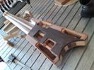
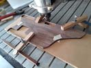
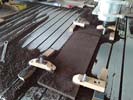
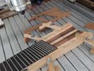
Setting up to cut a modified chember on the back of the bass. This will allow everything else to finally FIT!!!!
|
Left: The upper chamber has been re-sized and that will allow the pickup selectors to live next to the momentary switches and in doing so, make room for the controls and outputs at the bottom! Right: I discussed the electronic package in this bass with my electronics guru in Palm Desert today. Seems like the best possible plan!! |

I'm planning to have the bass stay at the electronics shop for a few days so that we can look at the best wiring plan, installation layout and get hold of any other electronic hardware needed to fit inside. When it returns from the finishing process we want to be ready to do a quick and efficient install of pickups and electronics.
|
|
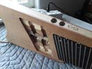
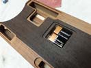
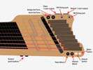
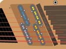
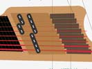
This is not physically done yet but will have to take place before finishing. I found away to include the rotary pickup slectors on the top surface next to the Roland program scrolling momentary switches. Parts are kinda expensive but I have no other way of getting all the required hardware in the bass. The good thing is that they will be easily accessible, they will not be disturbed or acidentally rotated while in use and since they will be recesses, they will be low profile enough not to be very noticeable from the front. Image is an artist's impression of the two knobs so they may end up a little smaller and closer together (they are only 12mm diameter)!
|
Left: I can't fit both 13-pin outlets + two stacked pots + two 1/4 inch jack sockets + two pickup selectors in the bottom cavity. I did find a way to install the selectors in low profile on the top! Right: Upon the CNC ageain this time to slightly re-size the upper chamber. This will allow all the electronics to fit into the body of the bass!!! |
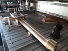
On the CNC where I am re-machining the upper recess. This will help tremedously.
|
|
Ifwe dont go active on the Piezo feed we will not oly have a very poor and weak signal but will have problems blending signals.
|
Left: Another detailed meeting with Mark, and in order to make everything work together the system HAS to be active. Good thing will be that power drain will be very low so batteries will last a LONG time. Right: My challenge is to somehow create enough room for all the pots and outlets on the body. I'm close but need to do some work. |

I need to get this bass into my finisher's shop as soon as I haveworked out all the electronic issues. My electronic dilemmas are mostly based on overcoming significant grounding issues with so many components inter-connected. Not an easy job!
|
|
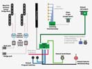
Current questions I am trying to answer: In passive mode, can I blend both pickup outputs to the Roland and retain the independent signals to the 1/4 inch jacks. This would, if possible at least give us Roland and Mag pickup blended options without having to go active.
|
Left: Mark has been informing me of the difficulties getting a usable piezo feed from a passive system. I want this bass to be the very best it can be, so looking very closely at both active and passive possibiities. Right: looking at the possibility of moving 13-pin outputs to the back end of the body as shown. I need to create more space! |
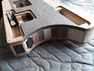
With all the controls required, and the finite amount of space, I would definitely benefit from moving the two 13-pin outputs to the far end of the bass, and in doing so, create room for all the other internal hardware. This is only a mockup to show the goals related to placement - in reality each output would have its own mounting plate for stability. Doing this would give me a chance to fit in all the other required controls.
|
|
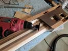
I need to get this bass into my finisher's shop as soon as I haveworked out all the electronic issues. My electronic dilemmas are mostly based on overcoming significant grounding issues with so many components inter-connected. Not an easy job!
|
Left: Working on the neck transition to get it finished. Goal right now is to get this instrument into finishing as soon as I can. Waiting on GraphTech for some additional technical stuff. Right: More sanding and shaping around the neck/body transition to get that nice and smooth and well blended together. Almost done with this! |
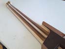
Doing some sanding to get the neck feeling as comfortable as possible - also sanding at the transition with the body to get that area ready for finishing.
|
|
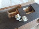
Two compact rotary selector switches which may solve many of our integration challenges in the wiring of this instrument.
|
Left: These took a little more time to spec out and locate but VERY happy to now have them. They can provide a very customizable choice of pickup selection options. Right: Two things going on right now. Cutting access through the headstock veneer for the two truss rods ends, and also sanding the neck to its final thickness and profile. |
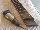
Ground out the access to the two truss rod ends -still need to sand it down and get it all cleaned up.Also sanding neck profile and some other areas..
|
|
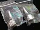
CGreat to get these controls in the mail. They will provide a very important space-saving solution for the magnetic pickup volume and tone controls.
|
Left: Just received one of the electronic hardware orders. These are special compact dual concentric pots wjich I will be able to use for the magnetic pickup feed. Right: I'm looking now at ways to incorporate the possible use of two rotary selectors suggested by Mark to give us an extremely flexible array of sound options! |
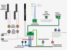
The electronics are complicated and work-intensive in this project for 3 main reasons. 1) All 3sound sources have to work together without grounding or signal strength issues. 2) Pickups need to have multiple selection options and go to dedicated output sockets while still providing magnetic signal feed through Roland. 3) Physical space based on size and shape of body is pretty limited, we are almost at the max!.
|
|

It was worth the drive to take the bass out to my electronic guy's shop so that we could evaluate the space we have to work with and how some of the controls might be best arranged.
|
Left: Brought the bass to my trusted electronics guy in LaQuinta and we discussed the hardware necessities to make the pickups, piezos and Roland all work together. Now have more hardware to order! Right: I simplified Mark's drawing a little bit to show what I think may be a super-flexible way to get the most out of the mag pickups! |
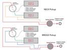
Customer wants to not only have the magnetic pickups go to separate outputs but also beable to separate the feed from each of the 4-string coils! Mark came up with this solution. I have to however make sure I can fit this in the body!!.
|
|
Mark and I are talking every day on this challenge. Passive pickups have a hard time integrating with systems that need to be active and we're looking at what electronic systems might provideus all with the right and most flexible capabilities.
|
Left: One of our challenges electronically is that the MIDI and piezo systems will have grounding issues working with the passive pickups and related switching. We are looking at what setup might avoid all of this. Right: Mark and I have put alot of development hours into avoiding electronic and grounding conflicts in the onboard systems. |
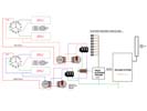
Getting close with some creative plans to make everything work. Mark gave me a drawing to evaluate in terms of fitting everything needed into the existing body. The two passive pickups need the most attention.
|
|
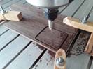
RCrazy day but I had a little time to create the lid for the (possible) battery cavity).
|
Left: Cut a matching Wenge lid for the cavity. Mark and I are doing everythig possible to accommodate all the switching requirements for the various sound sources on the bass! Right: Cavity and lid have now been established and we have a nice blended cover. This cavity will provide space for any batteries we may end up needing. |
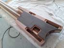
Battery cavity for two 9v units has been created should we happen to need that.
|
|
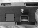
Keeping things moving - bettery compartment will be machined and I'll create a matching grain lid for it.
|
Left: Will be cutting a compartment for two batteries if needed. The cavity will have a perfectly matched Wenge lid attached with neo magnets so it will be very discrete when seen from the back. Right: Got the instrument lined up and clamped on the CNC machine table ready for me to cut out the cavity space for batteries. |
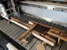
Ready to get this cavity cut. Glad I have some space I can use on the back. Will look fine with its matching grain cover.
|
|
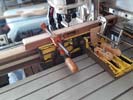
Just about to machine the two holes for the Roland program selectors.
|
Left: Got the bass up on CNC to cut the holes for the Roland scrolling buttons. I will do final fitting of the two buttons after the bass comes back from the finishing process. Right: Now have holes for Roland program scrolling buttons. Moving on to cutting a cavity and lid for the anticipated power for Roland and maybe GraphTech. |
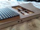
One more pre-finishing task done. Will get the rest of the holes in and finish neck and headstock carving!.
|
|
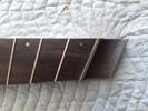
This area blends really nicely now. I still have to open the areas up for the truss rod access butdefinitely gived the headstock a much more finished look!.
|
Left: I ended up adding a black veneer on the string bending area because it was willing to bend where the Wenge would not! This matches the fingerboard material really well. Right: One area I know will not change is the two buttons that will be used for scrolling Roland through MIDI programs. Going to pre-drill for those! |
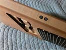
Ready to establish two holes for the scrolling buttons for Roland.
|
|
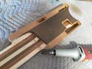
I want to get the back of the neck at the body shaped in such a way that the upper frets are as accessible as possible for the player's hand.
|
Left: I am waiting for feedback from Graphtech to see if I need 9v power to supplement the signals from the piezo inputs. In meantime I am finalizing neck to body carving. Right: Making calculations on what depth I have available for battery cavity since I have a strong feeling we will need at least one to keep everything active. |
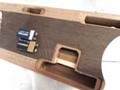
In my efforts to keep things moving and based on some feedback I am getting I will create a cavity on the back of the bass that can hold a couple of 9v batteries. If by some chance they are not needed it will be a gear cavity for picks etc!!!.
|
|

The Roland is a closed system that will do its job per their circuitry guidelines, but since we are trying to isolate pickup signals and bend some of the Roland rules, we are investigating. Similarly with Graphtech, the piezo signals need to be combined with other systems signals and I may need a specific circuitry! Mark has cautioned me that some of these systems may not work together without electronic conflicts.
|
Left: Based on some very helpful feedback from my electrics expert, I am exploring some electronic questions with both Graphtech and Roland to test the limits of compatibility! Right: Adding a veneer in headstock area to blend with the rest of the instrument. Also reducing the mass of the headstock area to a minimum before finishing! |
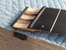
TI'm going top veneer this headstock forward area under the bending area so that it matches the darker grain on the center of the instrument.
|
|
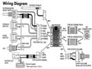
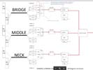
This is part of the Roland wiring diagram without the power supply components. We are investigating whether the circuitry will permit all the blending we want to achieve without the need for the Roland to have a 9v power supply. It gets complicated and I am very lucky to have a musical instrument electronic tech to assist me with this stuff!
|
Left: I am in frequent communication with my electronics expert, who has all the technical requirements for this bass. He is analyzing what the pickups, Roland and Piezo sources can actually do together. Right: I had consulted with my finisher and he use custom tint to mirror the back wood combinations on the front (artist's impression) |
My finisher saw the bass and can mirror the back colors onto the foront of the bass (which my customer really liked) so we are going to do that.
|
|
We're hoping to have piezo output from 8 strings to one of these outputs while the Roland MIDI feed comes out through the other. We are looking at the technical requirements of the Roland to see if this can all be achieved in a fully passive environment.
|
Left: I am setting the bass up to cut the recesses for the plugs that are required for the MIDI and the Piezo output signals. They will be held in place by two rectangular plates. Right: Slight changes to jack socket positioning to keep the plugs as far away from the player's hands as possible. Moving ahead carefully! |
It seemed very sensible to move the two 1/4" scockets as far from the player's hand as possible. We are looking at the various combinations of sound outputs right now - the Roland only really permits one wiring scenario so we're looking at ways to combine mag signals and piezo.
|
|
I'm final shaping and sanding the entire body of the instrument.
|
Left: I'm doing some final work in the fitting and sanding of the pickup cover/ramp which will be going to finishing with the bass and the other cover pieces for rthe back. Doing a lot of sanding! Right: Last thing I have to do to the body is cut the holes for the various sockets and controls. I'm starting iwth the MIDI and piezo units. |
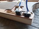
Now machining the holes that will permit fitting of the electorics after finishing is done.
|
|
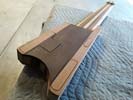
Three cavity covers have now been machined to very close to their final thickness. Last couple of tasks before finishing will be sanding the final neck thickness, and blending the transitions between neck, body and headstock area.
|
Left: Almost done with back of bass - I need to level the three cover plates flush with the body surface and then finish sanding the neck areas and we will be ready for finishing! Right: Cover plates have been finished for thickness and I am moving on to the final sanding of the neck and neck/body transition. |
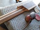
I am now sanding the back of the neck to get it to the optimum thickness and profile. In doing so I will be also working on the transitions between the instrument body and the headstock area too..
|
|
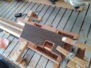
The back of the bass is now done with the cavity machining work. I will thickness and fot the three covers next and start some sanding work.
|
Left: Now have all three access holes cut in the back plate so I can get this instrument off the CNC and fit the covers and get some final sanding work done! Right: I am now reducing the thickness of the three covers so that we have a nice flat and complete back to this instrument. I'll attach these covers with small neo magnets. |
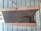
I will be machining and sanding the three covers to their final thickness.
|
|
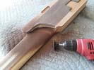
Grinding off the extra material on the beck plate to blend with the rest of the instrument.
|
Left: I left some overhang above the neck joint area so now I am sanding off that extra material so that I can blend the geometry of the neck to body area. Right: Now opening up the three cavity areas on the back such that we will be leaving a shoulder on each one for the covers to sit on and the placement of the retaining magnets. |
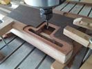
I am starting a little undersize on each one as I want some control on the final size that I end up cutting.
|
|
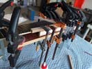
Gluing and clamping of back plate in progress. I will leave it overnight to make sure it all sets perfectly.
|
Left: Gluing of back plate under way. I was very careful to position it as well as I could. It will be really good to have this final part of the bass assembled!! Right: Back plate is now on the instrument and I am doing some surface cleanup at the moment. Then I will put the bass up on the CNC and mill out the cavity access areas. |
Back glued on - now I have to create the cavity openings and then I will finish necktransition and body profile.
|
|
Final sanding and alignment checks done and I am now going to get the back plate attached to the body.
|
Left: I did some careful marking on the body to make sure I am placing the back plate in the best possible position for the cavities below. I am not getting tooling together to attach the plate. Right: Setting up to get the back glued on. Quite a tricky setup as I want to make sure the plate is aligned accurately during the clamping process. |
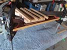
Everything always wants to move when you put glue on it and I don't have any places to drill locating holes & pins. Just need to take it slowly and it should work out fine.
|
|
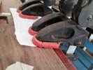
Carefully gluing the inserts intpo the recesses on the inside surface of the back plate.
|
Left: Now gluing the inserts into the back plate. Doing one side at a time to make sure the inserts are seated properly in theit recesses. Right: Back plate now has all its inserts done for the three covers. I will have to cut holes to match those cut in the back of the body but may do that part after the back plate is clued onto the body. |
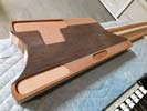
Back plate has been filled and leveled.All it really needs is asanding all over to clean it up from glue marks. I'd like to get this on the instrument body as soon as possible.
|
|
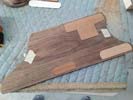
The three recessed areas inside the back plate have now had material fitted. I will glue these in and sand everything flush.
|
Left: I just cut some material in the laser which will fit in the back recesses and create the nesting for the three lids. None of this will be seen when the back is on. Right: Here's a quick photo of the other side of the back plate. When these inserts areinstalled I willmachine out the through holes and the back plate can then be attached. |
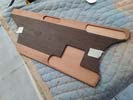
Back plate with the recessed areas for the three lids.
|
|
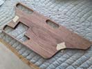
These three recesses should work out fine - I am anxious to get the back plate on the instrument and consider that part done!!!.
|
Left: OK - happy to say that the three recesses are done and I can now move ahead to what should be an easier task of cutting and fitting three inserts. Right: This photo shows the front and the back of the instrument side by side. Once I get the three inserts into the recesses I just cut, the back can be attached. |
I am in the process of creating the three filler pieces that will fit into the recesses I cut in the back plate. Will make a lot morse send whan I post the completed pictures.
|
|
First of the three recesses cut. I'll be installing material into these recesses which I hope to be able to cut on the laser. If not I can machine them on CNC.
|
Left: First cover hole is recessed - now getting the other two done. This will create nice neat covers for the back of the instrument held in place by magnets. Right: I'm now cutting the third and most tricky of the recesses due to fact that there is not a lot of spare material around the bottom of plate. Just have to be careful. |
Getting started on the third recess which I'll need to be very precise and careful with due to wall thickness.
|
|
Second wiring channel is done so I can start working on prepping the back plate and getting that attached.
|
Left: I machined the second wiring channel in the back surface. This one provides a little space for the wiring exiting the circuit board. I think these should be sufficient to the best of my calculations! Right: I am ready to cut recesses in the inner surface of the back plate. This will create pockets for the three cover pieces. |
Gettig started with the little switch cavity. I will becutting a recess into which I will glue afiller piece to create a step (around .150") for the lid.
|
|
Just about to machine a few wiring channels on the back so that the body is ready for the back plate to be attached.
|
Left: Setting up right now on CNC so that I can machine a few wiring channels in the back face, There are a LOT of wires coming and going from that PCB to different places on the bass! Right: Got the first of the back wiring channels machined which connects the PDB to the two Roland scrolling program switches. |
One of the wiring channels cut - the other one is a bit more involved but should work out fine..
|
|
Top pate now part of the instrument assembly and looks good so far. Need to do some cleanup sanding and then get wiring channels on the back finished up.
|
Left: Top plate now glued on as a permanent part of the body assembly. Now I have to do some machining to provide some wiring channels on the back of the body before back plate gets attached. Right: I am now sanding the perimeter of the body to blend in the edges of the top plate. Then I can cut those channels in the back. |
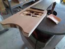
Using the spindle sander to clean up glue and blend the edges of the top plate to the rest of the body.
|
|
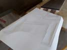
It's a quick safety precaution, but a paper impression of the milled out areas helps a lot once the top has been attached.
|
Left: Before attaching the top plate to the body, experience has taught me to take a paper impression of all the recesses so that I can know exactly where they all are after they are covered by the top! Right: The moment of gluing on the top plate has arrived. Next will be some cleanup and machining on the back face. |
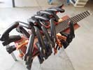
Top plate of the instrument is now being glued on. Once this is dried and set I'll clean up the perimeter and machine the back face of the body to finish recesses for wiring etc..
|
|
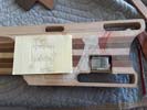
I am getting ready to cut wiring channels for the scroll buttons and mostly for all the wires coming off the PCB.
|
Left: Back wiring channels need to be cut. There are a LOT of wires coming off the board, many of which will go to the 13 pin output. I'm trying to plan the best orientation and wiring channel placement! Right: One more important operation under way - I'm gluing the dark veneer onto the joint face of the back plate of the body. |
I am gluing the dark veneer onto the back of the back plate.
|
|
To the best of my calculations this operation completes the work on top of the body and I should be able to glue on the top plate.
|
Left: Top wiring channels have now been machined. It was very importqant not to put a channel where a retaining screw would be, so everything has been as carefully planned as possible! Right: The back plate needs the decorative dark veneer applied to the inner side so I am going to get that done so that it can also be attached! |
Back plate needs two things - one is a dark veneer, the other is to have recesses cut for the lids. As soon as the veneer is on I will do that.
|
|
I will be machining these two channels for wiring related to pickups, piezos and grounding wires. Afther doing these the top can be premanently attached!
|
Left: I will be machining a couple of important wiring channels in the top of the body. Green is pickup wiring and red is a channel for Piezo and grounding wires. After that the top can go on. Right: Bass is on CNC for three wiring channels. Pickup wires, piezo wired and ground wires and also the wiring from the Roland pickup. |
I am going to machine a set of three wiring channels based on the anticipated locations of all the other controls.
|
|
Top plate in the vacuum press getting some dark veneer attached to the bottom (joint) surface.
|
Left: Now gluing a dark veneer onto the bottom surface of the top plate. This will allow me to get the top plate attached to the body of the instrument and it will yield a cool double pinstripe accent. Right: Dark veneer has now been successfully applied to the back of the top plate. It will be going onto the instrument soon! |
Dark veneer applied and cleaned up and now I have to cut a wiring channel on the top of the body. Once that's done I believe the top plate can be glued onto the instrument!.
|
|
So far so good on the cavities. Once I apply a veneer to the joint surface of the back plate (to match the front plate which already has one) I will do some machining to provide a location surface for each lid.
|
Left: Cavities ready, next two tasks will be putting a decorative veneer on the joint face of the back plate and cutting a few wiring channels in the back of the existing body. Right: I now have the back plate in the vacuum press where I am gluing on a maple veneer to match the top plate. May also do a dark veneer. |
Since the top and back plates are matching up with a maple center core on the body I will probably add a dark veneer to both top and back for a fancy double contrasting pinstripe.
|
|
This cavity will provide space for the Roland momentary scroll switches.
|
Left: Now cutting a smaller cavity which will house the two switches used for scrolling up and down through MIDI options for the Roland system. They should end up being pretty discrete. Right: Moving on to the third cavity which will house the rest of the knobs and switches required for Roland system and pickup blending. |
Third cavity will house potentiometers and switches. Once this feature is done I will set up for machining connecting channels for the wiring between all these electrical parts.
|
|
Each of these openings has to be recessed and then plugged with another piece of wood accurately cut to fill the recess. It will make more sense when I post pictures of the end results!.
|
Left: One of the other important machining jobs I have to do is to create recesses for the three lids on the back. First operation is to machine recesses in the back plate from the inside! Right: In this operation I am cutting out the lower half of the main control cavity where the output plugs and controls will live. Will move on to the other two. |
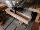
Now cutting the second stage of the control and output cavity..
|
|
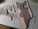
These lid pieces will be thicknessed and configured to fit beautifully into recesses in the back plate which Iwill be machining next.
|
Left: Lid pieces have been harvested out and I am now back on the CNC where I will be machining out the 2nd and 3rd cavities and also adding features inside the 1st cavity. Right: Bass back up on CNC so that I can finish machine the control and electronics cavities to full depth in the three locations. It will be great to have this done! |
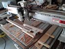
This is pretty much the last complicated machining task I have to do before I move to final shaping and other prep for the finishing process.
|
|
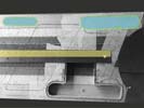
The two aread in blue/green are the lid perimeters and cavities for the remaining controls.
|
Left: While I have this specific setup on the CNC it makes sense to do the initial machining work to all three cavities on the back. I am going to go ahead and harvest the other two covers from the back plate. Right: Second and third cavities covers under way. It has been a lot of work already but results are mostly as planned! |
Removing the top two cover pieces from the back plate.
|
|
I would call this a success - the cover has been harvested out and I can now go ahead and machine other parts of this lower cavity.
|
Left: The first stage worked and I was able to remove the piece that will end up being the cover for this cavity. Now I need to get the first phase of the cavity space machined out. Right: First cavity machining cut complete. Got the Roland circuit board set in place with (I think) enough room for all the related wiring that comes from it. |
First op in the cavity done. Have a couple other cuts to do to finish this one.
|
|
Making the best possible decisions as we go here - it's all new territory and this bass requires a great deal of planning as we are very limited on space.
|
Left: OK - stop-press change of plan - I decided it was easier in the big picture to machine all the cavity features with the back plate attached so that everything could have a much better chance of alignment. Right: Into the unknown but I think it will all work out. Cutting through the back plate right now which I will remove when done. |
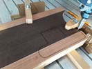
All this came to me while I was supposed to be sleeping last night - it makes more sense to get the cover cut and the cavity below it machined out in one opearion. Might do the other two this way. It will all make sense when I post more progress pictures.
|
|
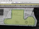
This is a vector drawing of the cavity shape and lid shape. Should leave a thin enough wall at the bottom for the 13 pin assemblies.
|
Left: Small adjustment to shape and size based on cover dimensions. I have to keep the 13 pin assemblies pretty close to the lower edge of the body. This should do the job for the lower controls. Right: This pic is just a shot of my toolpath for the main part of the cavity. I will create other paths for the areas that need to be a little deeper. |
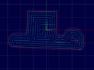
THis shows the toolpath for the main cavity. I will also create paths for the two sections that will be full depth plus lid cutout areas.
|
|
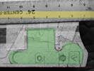
For anyone interested, this area in green is safe to remove material from the back of the body although the pots and 1/4 jack outputs will need to be cut deeper than the other areas!
|
Left: This photo shows the internal area I can afford to cut out to contain the lower controls (outputs and vol/tone pots) plus the Roland circuit board. There will be different depth levels for pots, 13pin and PCB. Right: Just about to run my CNC setup to cut the first cavity. Being as careful as any human can! More updates coming! |
I'm going to run the bottom cavity first. Might need a couple of operations/programs to allow me to customize the specific depths for the various features.
|
|
Will end up with two covers and two cavities of varying depths to house the various controls. I have another toggle switch to place somewhere but at least that will be small! Enough to make my brain explode and I will be glad when I have resolved and cut all of this!
|
Left: The upper bout of the body (as seen from the front) will have Roland program buttons, switch and blend pot in the same group so I should be able to keep cavity lids to only two. Right: I have the body up on CNC doing the 1st cavity, BUT may need to move the Roland program selector buttons to the side due to space constraints. |
As I work though this cavity issue I realized that my only reasonable way to accommodate all the controls is to move the two selector buttons to the upper side of the body. They are very low profile and to me it seems as if anything needs to be on the upper side it should be these two as they would not be seen and would free up some very valuable space!
|
|
I'm trying to determine how deep that first cavity can be to still akkow the 13-pin outputs to sit in place but still leave me enough material relief for access to the tuner knobs. Everything is so tight on this instrument there's no room for error!!
|
Left: The tuners will need a little relief under the knobs to allow access to them, so I have to be extremely cautious about not extending the lower cavity too far into that area. Right: OK I have the two cavities marked out. Took a photo of the areas and I will use that to scale and create the cavities in Illustrator! |
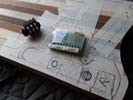
Spent a good chunk of the day on this as there are so many variables to consider. I wantto keep the lids to two if I cando that so I have to consolidate and arrange the electronics fairly accurately where I have space to do so!
|
|
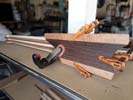
Have the back plate accurately placed on the center line of the existing body. Will cut and sand edges to match and then I can start cutting lid openings etc.
|
Left: I need to trim the back plate to exactly the same profile as the existing body so that I can then cut the plate for the cavity lids. The plate is clamped in the exact central location for me to do that! Right: After some sawing & sanding the back plate is now flush on all sides with the body. This helps greatly in setting cover placement. |
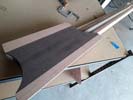
Back plate is now shapes and danded to accurately match existing body shape. I need that accuracy to position the cavity covers..
|
|
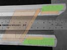
Brown areas are existing features (on the front of the instrument) and green are the areas I am working on to refine for cavities. Need to check on retaining screw lengths for tuners. Also will be establishing other areas for circuit board etc.
|
Left: I am drawing up an Illustrator file that places the cavities and covers on the actual existing perimeter of the body. This allows me to generate programs for machining each cavity and related cover. Right: The hardest part of the electronics placement is the area where the 4 output sockets live. Willneed to be careful in this area! |
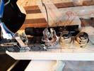
On the surface of the instrument the placement will look ok, in the cavity it will be very tightly packed. I'm looking for the most compact 1/4in jack sockets available. Those gld knobs are there just for my reference!
|
|
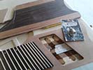
If I can verify all the hardware will fit in their deignated places I will get all the cavities machined accordingly. Stacked pots for Volume and Tone on the magnetic pickups look like they will be ok.
|
Left: The big thing right now is to make sure all the internal components can fit in the areas we want them to be in - I have some stacked pots so making sure these will work on the Vol/Tone positions. Right: Starting with the bottom cavity based on how close I can safely get the components to each other. If I am careful we will be OK! |
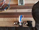
Establishing cavity perimeters and writing programs for them. It will be tight but I think we can place everything the way we wanted.
|
|
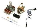
This is the Graph Tech option for no 9v battery. They also have a PE-0240 system but that is active and would require a 9v battery.
|
Left: I spoke to Graph Tech whose piezo systems I will be using. For a No-Battery solution they suggested a PE-0400 system where the piezos are simply summed and blended with the magnetic pickup output. Right: Objective is to have the piezo signals routed to a 13-pin output on the body. I'm adding that and working on wiring solution! |
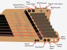
I believe that based on the sized of the various internal electronic components this is our bet bet for control layout. I have enough depth now in the body to use stacked pots for Vol/Tone on each pickup. Looks loike Roland stuff will fit in the upper back corner. Biggest components will probably be the two 13-pin assemblies and I am assuming the worst case on this drawing. It's enough data for me to get the cavities programmed!!!!
|
|
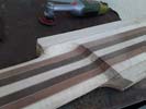
Establishing a final carved thumb space allows me to define the available material the set of upper knobs can start. Should not be a problem.
|
Left: When playing the upper frets there needs to be room for the player's thumb. I am cutting that to its maximum extent so that I can define the position of the furthest forward knob location! Right: Looking at the possibility of stacking the Vol/Tone on each pickup and moving those 2 to the more traditional location on the lower bout. |
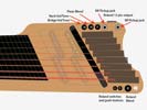
I'm checking and measuring to see if this could be done. It would be nice to get these controls in a more traditional location if possible. I talked to GraphTech regarding passive Piezo feeds from the bridge units - they told me they should be connected to magnetic output(s) via a special blend pot they make. This would perhaps help in us not needing a second 13-pin output but I will discuss with my customer.
|
|
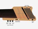
Audere has three stacked knobs but they have really small potentiometer bases which will allow me to place them on the upper surface of the body. I will have two 13pin and two 1/4in jack outputs. The 13pin circuit boards are bulky so it looks like the best distribution is as ahown above where there will be a jack socket between the two larger units. The two small blak Roland dots are ush buttons for scrolling through MIDI menu items. I'm looking at all the electronic packages right now to get a correct inventory of all the switches and knobs.
|
Left: Looking at all the controls for the instrument so that they can be laid out as close to my customer's preferences as possible. I'm doing an inventory of all the other necessary knobs and switches. Right: We have been updating the control layout options and this is closer to our ultimate goal. Roland controls MAY be able to move. |
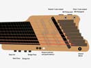
We are using passive circuitry for the two magnetic pickups and that allows me to make the top controls a little more discrete on the upper surface which helps me a lot. I'm also going to trt to use the available space to group all the Roland controls together.
|
|
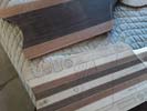
I'm guessing that I will have three cavity covers on the back to provide access to all the electronic components and battery power supply.
|
Left: I now need to make final decisions on the layout of the back access covers top the various components of the electronics in this bass. Not an easy task but one of the last before it goes to finishing!!!! Right: For reference - this photo shows the front and back of the bass. The whole thing will look awesome when the finish is applied. |
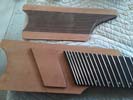
IPicture of the front and back of the instrument. The back plate has the same Sapele material alongthe edges and the Wenge part blends perfectly with the taper of the body laminates. The finish will bring out the grain of all these woods and it will look spectacular..
|
|
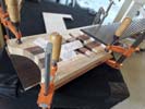
Marking out the final preimeter of the back plate after which I will rough saw the shape. This will all allow me to get back to the task of chambering out the body for the electronics and wiring.
|
Left: In order to guarantee good alignment with the other instrument features I am clamping the back plate onto the body in order to mark out my cut lines. I will then saw off the extra material. Right: Back plate has been marked and sawn slightly oversize. I need to do some trimming at the neck end to remove some material there. |
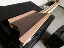
I'm working on the back plate now to bring it into size with the body profile. I can now define cavity areas and will use this plate to create blended continuous grain covers - should look very nice.
|
|
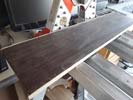
Maple veneer attached to both joint edges. Next I will be gluing on the Sapele.
|
Left: Maple veneer has been stuck to the edges of the tapered back panel. Doing some sanding to that and then I will add the additional pieces of sapele! Right: The veneering and assembly gluing of the back panel has been done and I sanded the whole thing on the drum sander to clean up. Looks beautiful and will do its job well! |
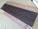
The cobination of the woods and the decorative veneer looks awesome and that's before any finish is applied. This panel will do an excellent job to provide fully blended access covers.
|
|
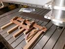
I am machining accurate joint faces onto the sapele side pieces of the back plate.
|
Left: I have the CNC set up to machine the joint faces of the outer pieces of the back plate. Once these edges have been cut I can add veneer and glue the entire back plate together. Right: I am gluing some decorative veneer onto the two outer edges of the wenge panel. This will reflect the other veneers I have used elsewhere on the bass. |
Gluing maple veneer to the two side joint faces of the wenge back plate. When that's done I will glue the two outer pieces on and sand everything nice and level.
|
|
Cutting the ptapered shape of the Wenge to match existing geometry on the back of the bass.
|
Left: Machining the taper of the central piece of Wenge I will use for back plate and cavity covers. When this is done I will glue on the sapele pieces to make one complete assembly. Right: The center piece has been cut and I will now be adding the two Sapele sides (and most likely some decorative veneer) to complete the assembly. |
Tapered center piece has been cut and I will go ahead and assemble the Sapele sides..
|
|
I will be doing a couple of machining operations to this piece of Wenge and ultimately adding the two Sapele side pieces.
|
Left: Setting up the central piece of African Wenge for the back plate assembly. I'm going to machine the thickness of the plate dwn tpo about 5/16 inch thick and then I will machine the tapered profile. Right: Machining this nice piece of wenge down to match the thickness of the sepala pieces I will be adding to the sides. |
Machining down the Wenge to metch the thickness of the sapele.
|
|
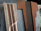
I have some Sapele left over from the top plate material and I am planning to combine that with some wenge to create a very fitting artistic back for the body inside of which I can creat all the required contuinuous grain covers!.
|
Left: Looking at some cool woods I have in stock re. the back plate. This would be an elegant solution to the cavity/cavity lids dilemma AND allow me maybe 1/4" more cavity depth to play with! Right: I am now measuring the areas on the bacl so that I can cut and machine the sapele and wenge to create a geometrically matching back. |
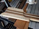
These two woods should combine to do a beautiful and artistic back plate which will also incorporate continuous grain covers!
|
|
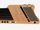
I'm busy quantifying how many pots and switches will actually be needed to make this thing work. What is shown in a minimum configuration. Also actual locations not yet finalized. A is Audere, R is Roland.
|
Left: I have selected a few areas where I am going to cut initial cavities for electronics and wiring. I will be moving forward carefully establishing these in the body. This illustration shows most of the required controls. Right: I am looking at possibly adding a fairly thin decorative back plate so that I can create matching wood cavity covers. |
The back plate would be a huge help to placing internal components and will allow the addition of beautiful decorative continuous grain covers.
|
|
I have 4 outputs to configure in the lower right area of the body- working on that right now to make sure I have space for all of that hardware!!.
|
Left: My big goal here is to get the rest of the cavities machined so that I can get this instrument off to finishing. It will come back looking awesome and I will then be able to dig into all the electronics. Right: I can create cavities for most of the electronics that need to be in this body & calculating whether the body thickness is adequate. |
I do have space under the pickup area to create some space for electronics although I don't want to weaken the structure that has to hold up to the string tension. I'm wondering if it would be wise to create a back plate which would then allow me to create as many lid/covers as needed while helping add a little thickness to retain core strength. I love the laminates on the back but if I cut cavities in that I can't make matching lids. I may have some really nice material I can use that would look just as good. Lots of stuff in a very small space.
|
|
I think I got the recesses deep enough to work on the finished assembly. There are 8 wires that now need to have some clearance machined so they can pass through to the control cavity area.
|
Left: Bobbin relief in the body has been machined. I need to now do some test fitting to set the best area to allow the wiring to be channels through to the area where the controls will be. Right: Working on the wiring channels under the top plate so that the pickup and other necessary wiring can run to the correct places! |
I will be running 4 pairs of wires from the magnetic pickups, a wiring cable from the Roland pickup, six piezo wires and eight grounding wires from the bridge units. I have to account for everything that needs clearance or channels under the top plate.
|
|
I was right in the middle of cutting the pickup recesses when the old computer failed. Got hold of a replacement and busy setting it up and installing the software. Like I had nothing else to do today!
|
Left: I'm in the process of upgrading my CNC computer today - the old one decided it was not going to all the work for such low pay and it quit on me yesterday! Right: Now machining the relief for the pickup bobbins under the ramp area. I will need to do a calculation to decide how deep to go with these recesses but so far so good. |
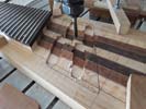
Machining pickup relief into the instrument body.
|
|
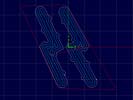
Once this relief pattern has been cut out of the body material I will be able to test fit the ramp/pickup assembly and make sure everything lines up and fits.
|
Left: I did some CNC programming so that I can cut out the relief for the lower half of the pickup assemblies below the ramp. I'll get this on the machine and get it all cut out asap. Right: The instrument is now up on the CNC and I will be cutting out relief for the lower parts of the pickups as they are laid out under the ramp we created. |
Getting ready to cut pickup recesses!.
|
|
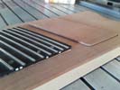
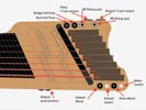
This photo shows what the pickup ramp is planned to look like after all this hardware is installed..
|
Left: This picture illustrates a little better what the ramp will end up looking like when fitted into its recess on top of the body. Right: I have been creating a layout that allows me to place the output sockets in the required locations and also house the Roland and RMC electronics plus the various pots, battery locations etc. Crazy! |

IWhen I cut the recesses for the pickups in the ramp piece I made sure to keep the wood about the top surfaces of the pickups quite thin (around .050"). This allows the internal pickups themselves to be adjusted upwards as close to the strings as possible. There will be adjustment screws and springs etc to make the ramp behave just like one oversized pickup.
|
|
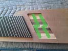
I will be machining clearance below the ramp for the bottom of the pickup array to provide the right height and adjustment range. I will also machine wiring channels before the top gets glued on.
|
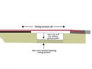
Left: With a clear picture of the placement of the 4 pickup bobbins I am now modifying the locations for all the remaining internal bits and pieces so that I can cut cavities in which to house them all! Right: A slightly simplistic illustration showing a side view of body and the ramp/pickup assembly's relationship to body/strings. |
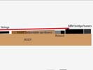
IWhen I cut the recesses for the pickups in the ramp piece I made sure to keep the wood about the top surfaces of the pickups quite thin (around .050"). This allows the internal pickups themselves to be adjusted upwards as close to the strings as possible. There will be adjustment screws and springs etc to make the ramp behave just like one oversized pickup.
|
|
I could probably also use hot glue to make sure these pickup bobbins are very solid. Have a few options. This is ALL unknown territory so we will see what's needed as we assemble the ramp.
|
Left: This photo shows the first of the four pickup bobbins fitted into the correct recess. Nice and snug and I will be adding small screws to make sure these bobbins are held securely. Right: I fit all 4 bobbins into the ramp and I am now looking at the possiblity of attaching the top plate to the body. Some wiring channels to cut first though. |
This photo is a testimony to accurate machining. The four bobbins fit in there just the way I wanted them to!
|
|
I just programmed the locations for the four pickup bobbins! Ready to do the machining..
|
Left: I am getting ready to machine out the recesses on the back of the ramp plate. Goal is to leave about .050 to.060 inches of material at the bottom of each of the recesses. Right: I'm working carefully on the back of the ramp to establish the four pickup biobbin recesses. Tricky job with very tight tolerances!! |
INot mucg room for error on the back of this plate! Wish me luck!.
|
|
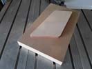
MDF ia a great material for incidental fixtures like this that I will only use one time. It will guarantee correct placement of the machined features.
|
Left: This nice chunk of 1" MDF is going to be my fixture for the remp machining. I have a drawing and a program already made for this so I'm getting ready to set up and do the machining! Right: The cutting of the fixture is under way. I'll use this to accurately locate the underside of the ram for the machining of the pickup recesses. |
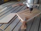
Cutting the holding fixture on the CNC.
|
|
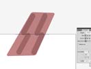
First job is to cut recesses in the back of the ramp to locate the pickups and place them as close to the strings as possible.
|
Left: Next challenge is the placement and machining of the four recesses for the pickup bobbins. I'm starting in a vector program and creating a CNC program from that. May need to make a fixture. Right: I am creating a recessed fixture so that I can safely hold the ramp piece while the pickup cavities are being machined. |
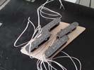
I wanted to see the actual pickups on the back of the plate - will keep them near the machine to make sure everything fits!.
|
|
This operation will separate the ramp material from the rest of the top plate.
|
Left: I set up and machined a fixture that would hold and position the top plate in the correct location and I am now machining the ramp perimeter from the back side of the top plate. Right: Finally - ramp plate removed from top plate - everything went well and now I can work on creating recesses in both body and ramp for the 4 pickups!!! |
Made it this far. Next I will be machining the back of the ramp in order to fit the 4 pickup bobbins in place.
|
|
I have to make these cuts in several passes to avoid the little carbide cutter breaking.
|
Left: Making the commitment to machining out the ramp. I am using a very small cutter to minimize the material removed and optimize the fit when we're done. Going very carefully. Right: So far so good - this pickup area is very carefully designed to keep the 4 pickups as far apart as possible for optimum performance. |
IThis is the first cut - about 1/4 inch deep.I need to reset the top plate on the CNC and machine from the back to release it completely. Then I will machine the ramp to house the 4 pickups.
|
|
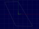
This profile is a result of aLOT of measurement and calculation related to all the features that need to exist between the bridges and the neck.
|
Left: After the recent adjustments this is the final path for the ramp which I have now programmed. I'll get this cut and probably make a template for further machining. Right: I have the top set up on the CNC to cut the ramp profile. I have a print of the ramp to scale positioned exactly where it has to be to facilitate setup positioning. |
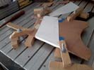
I will use a very small .031" cutter to machine as deep as I can round the ramp. I'll need to flip it over and machine from the back to release it.
|
|
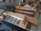
Setting yup to clean up and square off a couple of fairly important reference surfaces.
|
Left: On another area of my CNC table I am setting up the body in order to clean up a couple of surfaces at the end of the neck. Need to have everything fit just right with no room for error!!! Right: This is the first of a few machining operations on the top plate. Right now I am cleaning up the neck joint angle for positioning. Next will cut ramp. |
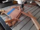
Since I need a greater than usual degree of accuracy on these features I'm making sure top/neck joint is accurately set before positioning and cutting ramp area.
|
|
This appears to be the best compromise for the ramp shape. Next move is programming and cutting it out of the top plate.
|
Left: This is the area (white) that all these measurements and calculations has yielded for the extent of the pickup ramp. It leaves space for Roland pickup and a little finger space for slapping. Right: I have written a program that will allow me to harvest the ramp plate from the top plate of the instrument. Just need to position it and get it cut. |
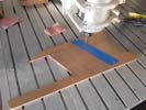
Working on the CNC setup where I will be cutting the ramp plate out of the top plate.
|
|
I'm checking with Mark to see whatthe absolute minimum distance can be between the two sets of pickups. I could always create more space by shortening the fingerboard by 1 fret but I would much rather not do that!.
|
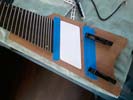
Left: That blue tape against the fingerboard is about one inch wide. I'm hoping that will provide enough finger space for slap-style playing since the pickups need to be separate enough not to affect each other. Right: I have established limits for the ramp and looks like I can go ahead and get that ramp shape cut out from the top plate. |
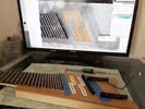
Doing some actual measurements while duplicating the correctly sized components on the computer. Difficult job.
|
|
While I am working on all the top features I might as well add this little nameplate to the list!.
|
Left: Very little space on this instrument to add the brand name and serial so I may place it on a recessed section just behind fret 30. It wont get in the way of finger space as it will be almost flush with top surface. Right: Here are the parts in place showing us what we can get away with space-wise. It's close but I will do my best!!!! |
On the right side we have the tunets whose positions are pretty much fixed based on scale length requirements. On the left we want to leave a little finger space for slapping style playing. In between those two points we have a Roland pickup, the side walls of the ramp (which can be pretty thin) and two pairs of pickups which can't be too close to each other because of phase/polarity issues.
|
|
The top plate will have the ramp section machined out and that piece will have some machining done on the underside. I'll also have corresponding recesses machined for the pickups in the body below the ramp. I have to be very careful about placement!.
|
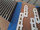
Left: I'm going to be working on this top plate to get the ramp cut out and machined. Doing some measuring and programming right now so that I get everything in the right place! Right: I cut the pickup shapes out on the laser (easier and safer than using actual pickups) so that I could verify placement and alignment of each. |
These replicas of the individual pickups will help me verify a few things related to the shape and size of the ramp.
|
|
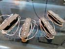
Got the second pickup array from Mark and I now have what should be a great source for the magnetic pickup signal on the bass.
|
Left: I got the set of new pickups from Mark. This is about as custom a set of pickups as I have seen but glad we got through all the work and I have these on hand now. Right: Now that I have the actual pickups I can finalize the ramp preimeter and get that marked, programmed and cut out! Should be exciting to see all this happen! |
These are the new pickup units placed in the body and the resulting ramp perimeter drawn around them. I will be using this geometry to get the blank cut for the ramp area.
|
|
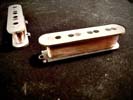
Heard from Mark that these bobbins have exactly the desired output levels and based on their copper gages and windings are well balanced. He need to add wiring and get then potted after which I will find a way to get back over there and pick these up!.
|
Left: Pickups have been wound with nice even output and so far this revision of them is giving us good output measurements. They are about to be finished up and potted. Right: The four pickups have now had their terminals installed and output wires connected, then taped, insulated and potted and re-tested. |
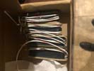
Mark has been amazing in this very difficult process of creating custom pickups for me. Looks like we finally have a set that will work in this unusual bass.
|
|
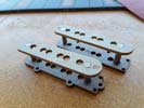
These are the redesigned pickups in the process of being assembled. Bottom bobbins allow me a means to attach the bobbins to the ramp plate.
|
Left: These are the bobbins with the revised engineering in order to give me a way to fix them to a ramp plate from underneath. Lots of inventing going on here to achieve desired results. Right: Winding on the recently revised bobbins has been done. I'm waiting to hear from Mark how their output properties measure up. |
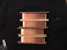
My feedback from Mark on this batch is good so far - he is winding in such a way as to make sure the output from each set is suitably balanced. He has out a lot of work into this!!!.
|
|
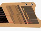
OK - this pic shows the ramp area plus the pickup placement and spacing. I need to devise a way to lock the pickup bobbins into the ramp so that they are fixed firmly to the top surface. It's a complicated job..
|
Left: Back to the pickup ramp work - firstly I will be cutting out the ramp piece based on the pickup and Roland unit placement. After that I need to machine recesses in ramp and into body. Right: OK - after consultig with Mark I adjusted a few things so that the bobbins and the ramp will lock together better. This is all very complex work. |
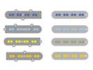
I'm adding a clamping system to the bobbins to facilitate the locking of the pickups to the underside of the ramp. We're breaking a lot of new ground here and adjusting as we go and learn.
|
|
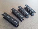
Bobbins are complete! I now need to get them to my winder who is a couple of hours away.
|
Left: I have all the magnets installed in the pickup bobbins and now I have to get them to my electronics guru for winding. Will be heading there soon. Right: I had a chance to drive to my electronics guy in La Quinta so I brought the pickup bobbin assemblies to him so that he could work all his magic to them. Looking forward to getting that done. |

He's not real close but it's wirth the drive. I go through the mountains on smaller roads as it;s quicker than dealing with the freeway traffic!.
|
|
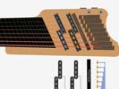
We had flipped the layout of the bass pickups but, as a result of exploring this from an electronics point of view, it will cause out of phase issues and I have been strongly advised to stagger them as shown for best results!.
|
Left: A feature we were hoping to include turns out not to be advisable. I had to revert to the P-Bass pickup layout because the "flipped" layout I illustrated earlier will cause phase issues. Right: I am assembling the for pickup bobbins with their magnets so that I will have a full set to take to my winding subcontractor. Getting there! |
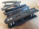
In the middle of assembling the pickup bobbins and magnets!.
|
|
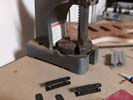
Assembling the four pickup bobbins.
|
Left: Collecting all the magnets and other tooling so that I can assemble the four pickup bobbins.Once they are assembled I will have them copper wound and potted. Right: I have a scaled drawing of the layout area for the pickups. I'll create this from the parent material of the top plate of the body. Should work & look fine! |

I roughly laid the bobbins out to see how they looked on the top of the bass.
|
|
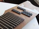
I roughly laid the bobbins out to see how they looked on the top of the bass.
|
Left: Just wanted to roughly show the pickups as they will be laid out on the top of the instrument. Should all work out fine. I just wanted to see how they looked in place so though I would share! Right: Working on the geometry of a ramp area under which these pickups will eventually live. Calls for some creative machinery :-) |
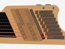
II may modify this geometry slightly but basically it will be a plate under which all four magnetic pickups will live.
|
|
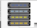
Each pickup is unique in terms of string spacing so I have to make sure they are labeled for the laser!
|
Left: This is what all 4 magnetic pickups look like. They are colored just because I don't want to get the pole spacing mixed up. I'll be creating these on the laser. Right: I cut all the required bobbins for the two sets of magnetic pickups based on last engineering changes. Good to have these and I will be assembling them with their 32 magnets! |
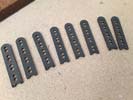
Cut the bobbins on the laser and they are now ready for assembly!!
|
|
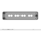
Slight re-design of the bobbins so that I can keep them as compact as possible. It would be nice to just buy commercial pickups for this but because of the pickup angles, the small body and the need to save space plus the desired sound characteristics, there is no way I could purchase something like this. I am lucky I have a laser and I can custom create objects like this!!
|
Left: In order to keep bobbin/pickup size compact I re-designed the placement for the adjustment screws so that I only need three screws for each. This shoudl help a lot! Right: OK - this is the result of the recent engineering mods - I think it will work really well so I am going to go ahead and cut the whole set and keep moving! |
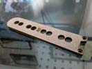
I cut the new bobbin design and it seems that it should work fine. I'll be testing it in custom covers soon too. Should look and sound good!
|
|
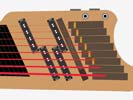
TThe magnetic pickups will need height adjustment so I am looking for the smallest screws I can find that will do the job so that I can keep the pickup sizes assmall as possible since we want a lille slapping finger space near the fingerboard.
|
Left: I am now getting ready to cut bobbins for these pickups on the laser. After cutting I'll assemble with magnets and have them copper wound. Also looking at the best way to add height adjustment screws on the covers. Right: Test cutting pickup bobbin to evaluate several things. Want to keep these as compact as possible. |
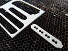
I cut a pickup bobbin to see if it's compact enough to work on the bass, but big enough to take enough copper winding. Also need space for the little wire terminals. This will tell me a lot and help me build these with confidence as they need to be fairly custom assemblies.
|
|
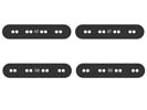
These bobbins and pole spacing are a product of my calculations. Now I have to manufacture the bobbins and collect 32 magnets.
|
Left: Based on my recent calculations these are the 4 pickup bobbins we will be creating. I'm leaving enough room on them for plenty of copper wire so that they are nice and hot!. Right: I happened to bring the bass from my shop inside to my clean room workbench and noticed that the side dots were glowing! Thought I would take a photo. |
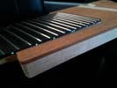
The side dots got some daylight from my workshop and I noticed them glowing when I brought the bass indoors.
|
|
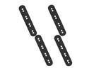
The placement and string spacing of the poles are important factors in laying out the phyical design and sizes for these pickup bobbins. I need to also leave enough space so that we have room for the best copper wire type/gage and number of windings. I will be cutting these soon on the laser.
|
Left: Now that I have a plan for pickups and electronics I can work on the string spacing and physical design of the two sets of pickups so that I can cut the bobbins and get these wound. Right: I calculated string spacing based on string gages and from there I was able to place the pickup pole placement at the required pickup angles! |
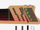
All these calculations end up giving me the correct spacing for the poles on the pickup bobbins.
|
|
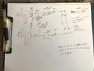
Mark was kind enough to send me some thoughts on how we might deliver all these different sound sources through the 4 outputs on the instrument. More on this coming.
|
Left: I heard from my electronics guy that the overlapping pickups will yield different output volumes and will present problems - much safer to go with full 8-string pickups or pairs of 4. Right: Now that we have a better concept of how the magnetic pickups might be configured I have to look at the wiring challenges that will be involved. |
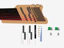
It helps to know the magnetic pickup plan. Now I have to look at the challenge of how all these sound sources can be connected together and how the physical electronic components are inter-connected so that they can be built into the existing body of the instrument. I'm making a diagram of hardware for Mark so that we can study all of this.
|
|
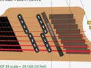
We might do a reverse arrangement on the neck pickup setup. Also decided we could add a small extension to the Roland pickup to balance the visual appearance.
|
Left: My customer asked me if we could stagger the bobbins on the neck pickups to maybe gain a little tonal advantage. I'm not seeing a problem with that. Right: My customer asked me if I can possibly extend the split pickups to six poles/strings each. Working with my electronics guru to see if that's something we could incorporate. |
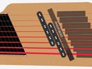
I don't know if we can do this yet but waiting to find out.
|
|
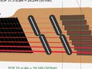
Just another option for the magnetic pickup layout so that we can provide the best and most diverse sound without phase issues or compromising body strength against approximately 600 lbs of total tension from the strings!.
|
Left: I also have access to commercially available 4-string BLADE pickups. These could be arranged as shown in the photo. Any of the 4 configurations below is possible based on my interaction with Mark. Right: Because this is such a complex project electronically, Mark and I decided to test wind an 8-string pickup bobbin and see how it works out. |

Just another option for the magnetic pickup layout so that we can provide the best and most diverse sound without phase issues or compromising body strength against approximately 600 lbs of total tension from the strings!.
|
|
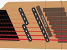
This image shows the combination of a single and a split pickup combination.
|
Left: Another option for us is to have one straight 8-string bobbin and have the neck pickup be designed a little like a P-Bass split pickup using two 4 string bobbins. Right: And a third option would be to split both pickups.Makes winding easier but the combination does occupy more space. Still leaving room for a little slapping space at neck. |
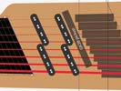
In this picture it shows two sets of split pickups.
|
|

I am machining a wiring exit slot in six of the AMB tuners for the piezo wires.
|
Left: I am in the final round with Mark looking at what options he can provide me for the best tonal output for this bass monster. We have narrowed down a few things. Right: After exhaustive discussions about pickups in this 3" space, for the sake of the best sound from this bass Mark and I are strongly suggesting fixed separate pickups. |
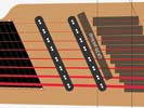
According to Mark we CAN wind copper on an 8-string bobbin so we do have a choice of creating two pickups similar in shape to J-Bass style. Doing this also avoids the possible structural cross section weakness of the sliding pickup recess that I was concerned about under the tension of 8 bass strings.
|
|
The blue area is the body shaope as it is right now. Brown area is the anticipated slightly shortened body shape. Green is the area of the revised body shape that is recessed for finger access to the knobs. For anyone looking at the bass the green area would appear as part of the body.
|
Left: I hope this photo makes sense. I am showing three areas. Original body shape, reduced body shape and recess area on reduced body shape below tuner knobs. Right: Six of the tuner units have to have special piezo saddles installed and to aloow for this I have to machine a slot in the bottom of each unit for the signal wire. |
I am machining a wiring exit slot in six of the AMB tuners for the piezo wires.
|
|
This would work great from a manufactureing perspective but required too much linear space. I asked about reducing the same system to a 4 pickup layout to see if it would fit in the 3" or so that we have to work with. It might but he pointed out that if that were the case we'd be better off with the tonal diversity of two separate 8 string pickups.
|
Left: Mark had a concept for a pickup array housed inside the elongated cavity but we discovered that it would need to be about 6" in length to avoid magnetic field issues. Right: Something that occurred to me in all this intensive pickup conversations - I have a very narrow body with 8 strings of combined tension. Looking at the physics... |
The geometry of this bass with its narrow body and the combined tension of eight strings brings up a few questions about inherent strength IF we machine out a big cavity for sliding pickups. Most of the 8 string tension will be transferred to the area of the body below the pickup recess.
|
|

Mark and I are in regular communication to find the best way to produce a detectable difference in tone using the 3" wide space on the instrument. Given that a pickup has to have a magnet large enough to overcome the difference in string spacing, a copper coil with a minimum of 1/8 buildup and bobbin to provide spacing an clearance, the distance a pickup can move within that 3" space would be around 2.25" Based on the flux of a vibrating string that distance of travel yields a fairly subtle difference in tone. Mark has a concept he is working on of his own design to overcome this and the inevitable phase/signal challenges.
|
Left: Main restriction in using a pair of sliding pickups is that no matter how they are designed there will be a phase issue when they are close to each other causing an imbalance in output. Right: I sent drawings to my electronics guy to seek some more information on the different options we might be able to employ.. |
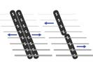
I sent these pics to Mark with a list of questions so that I could better understand his concerns. I will be updating this page as I learn and develop solutions with him.
|
|
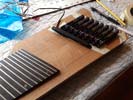
The tuners have to be in fixed positions based on relative scale lengths but that still leaves some material that can be removed from the very back of the bass. The objective is to do that while retaining the curved feature. Roland pickup can't be more than 50mm from bridge locations. I have to bear in mind that the lower strings will have a lot more backward intonation adjustment but as long as the pickup is parallel and close to the tuners it will remain within that range.
|
Left: While Mark is pondering over pickup criteria I have been finalizing locations of tuners and Roland pickup on the body. I will be trimmimg off a little from the back of the body contour. Right: In my ongoing dialog with Mark, he is suggesting that we could maybe make it work with two bar magnets (4-string each) under special conditions.. |
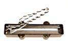
We are thinking that if we have two bar magnet pickups (somewhat similar to above) moving independently this would hopefully defeat loss of volume and tone as the string separating varies from front to back of travel. Mark indicated that tp avoid out of phase issues they would need to act as single coil when separated and humbucking when aligned together.
|
|
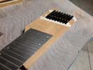
May be able to reduce the length of the body slightly once I have done some calculations based on positioning of tuner units.
|
Left: Checking now using ABM tuners to establish how much material I can safely remove from the back end of the body. Lot of calculations involved based on scale length and intonation adjustments. Right: I have been having regular emails with my electronics expert to discuss the details of how to achieve the sliding split pickup. |

Mark is working on finding a way if possible to avoid two 4-pole pickups causing phase interference with each other. They also need to track the natural taper in the strings.
|
|
The tuners actually cost more that the finishing process. ABM have been very busy over in Germany as they are the only ones with a proven ptroduct like this.
|
Left: I ordered eight of these tuners and recently checked with the supplier. They were fairly sure they would be able to get them for me in time for the post-finishing phase of this bass. Not cheap but best option on the market. Right: Very happy to announce that my set of 8 ABM tuners has arrived safe and sound. Thank you ABM! |
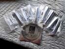
Well. I don't have to worry about these any more. I had heard that they are hard to get and ABM have been saying repeatedly that they are out of stock and it would be some considerable time before they ware available again!.
|
|

The green area on the photo shows the area occupied by the tuners. We may slightly modify the end shape of the body.
|
Left: I anticipated that the Roland pickup would be fixed at its Roland recommended distance from the bridge units. I'm calculating the sliding pickup recess based on that and some finger space at the end of neck! Right: With Mark's help I am better able to visualize how these two sliding pickups might interact. Tricky but do-able I think. |
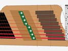
Two 4-string groups of individual puckup modules which will be compact enough to pass by each other. More info on all of this coming soon..
|
|
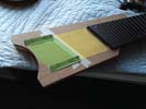
The green area on the photo shows the area occupied by the tuners. We may slightly modify the end shape of the body.
|
Left: We are taking a quick look at the back of he body and its size/shape relationship with the tuner array. We may remove a little more material to bring the backshape inward slightly. Green is tuners, yellow is the pickup recess area. Right: It looks like I can shorten the back of the body a little which I will do after I fit electronics. |
I hope this image can illustrate the difference - based oin tuner locations I can take off a little bit at the end of the body.
|
|
Working on a very unique pickup design. Best scenario is an 8string split pickup that allows two separat 4-string sections to travel forwards and backwards. Some electrical engineering involved!
|
Left: I have been discussing the split pickup scenario with my pickup expert and we are developing something that might work. We're looking at all the technical stuff right now. Right: The pickup dimensions and poles may be able to be altered to make the pickups a little taller. We think this will reduce or eliminate the overlap. |
Tentative design on special pickups for this bass. We are currently working on actual string spacing to verify that the laws of physics will allow us to do this.
|
|
Not the cheapest or technically easiest solution since it requires the winding of four smaller pickups but it seems to be the closest formula to the goal.
|
Left: I have given this whole thing a lot of thought. In my opinion the best way to achieve the sliding pickup solution is to have two narrow 8-string pickup assemblies using ploes or blades (blades perhaps better) and allow these to travel together or separately to produce pretty much any tone combination. Two half pickups can't really cross oe overlap each other's path because of the necessary conflict of individual coil windings. |
|
I have to cut out a piece of the top plate and use that piece as the bottom of the pickup recess. To do that I am carefully establishing the maximum area the pickup parts can live in.
|
Left: Establishing the area I will be machining for recess in which the pickup components will travel. This is based on scale length and the physical sizes of the bridge/tuner units I will be using. Right: While I am planning out all the recesses needed in the revised body I am also working on the best way to design a split pickup geometry. |
Because of the necessary overlap of copper winding it's not easy to creat e a split pickup where the travel on each half is able to overlap the other. Working on a few ideas - will update.
|
|
IBody is much more compact now. Next I have to look at the pickup recess based on maximum travel and how that split pickup is going to separate.
|
Left: I have carefully machined the upper and lower body edges to a finished condition. This in turn helps me get more material removed around neck both at body and headstock. Right: I'm working on the final shaping of the headstock. I'm removing material to a minimum condition with the fit and function of string retainer in mind. |
Body is much more compact now. Next I have to look at the pickup recess based on maximum travel and how that split pickup is going to separate.
|
|
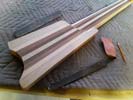
Machining the outer (straight) edges so that we have finished surfaces on the top and bottom surfaces of the body.
|
Left: Setting up to do some trimming along the top and bottom edges for the body to finish that up. I will also be working on the other features around the perimeter. Right: On the CNC so that I can establich a clean finished edge on upper and lower body edges! Bass a little bit lighter thank to removal of extra material. |
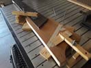
I was able to do it this way thanks to having a milling cutter with long flutes.
|
|
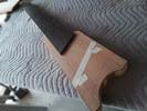
Body is now trimmed in line with the angles of the sides of the neck.
|
Left: I went ahead and trimmed the body to make it slimmer per my customer's preferences. I will plan recesses in the resulting body shape to house the various electronic parts! Right: Setting up the CNC tp add threaded holes to the string retainer so that I can install set screws which will give us the string clamping capability. |
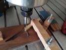
Had to make anothere custom fixture to allow me to accurately place the threaded holes for string clamping!.
|
|
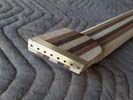
Retainer is drilled and fitted. Needs clamping and retaining screws but I can shape the remaining headstock material to reduce to the finished size and shape.
|
Left: The string retainer is drilled and I have a few other features to machine into it, but the main thing here is that is allows me to get the rest of the headstock shaped down. Right: Based on the fact that I will be trimming material off the sides of the body I have to be VERY careful about the placement of the electronic components. |
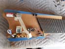
There is going to be very little room for electronic hardware and wiring inside this bass. The sliding pickup components and large recess they require will use up a lot of real estate.
|
|
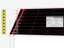
Got things set up for the string retainer - I only want to do this once!.
|
Left: In the very careful process of drilling the eight string through holes at a specific angle in the custom string retainer. I'm doing it on CNC for guaranteed positional accuracy!! Right: In the process of drilling the eight string holes into the string retainer. All looks good so far. I'll remove when done and finish on drill press. |
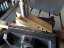
Drilling the holes into the retainer. I'll need another little fixture to get the tapped holes for the clamping screws done too.
|
|
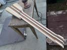
Lots of sanding going on but it wgets me a lot closer to finishing.
|
Left: Lots of sanding and carving going on here but it will be worth it to have all these intersecting shapes much closer to finished sizes as I will have a good amount of final sanding to follow that! Right: Did a fairly well thought out and accurate little fixture on the CNC to allow me to get the string holes drilled through the string retainer. |
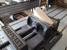
This holding device has to hold the string retainer very firmly at just the right angle so that I can use the CNC to drill the 8 string holes.
|
|
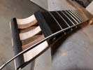
The length from bridge to string retainer is fairly important based on string winding diameters.
|
Left: Testing the winding length of a .168 string against the overall bridge to headstock length of the bass. Looks like everything should work out for string compatibility. Right: I'm now doing some carving on the back end of the neck/headstock to reduce mass in that area. Also involves a little more material coming off neck profile. |
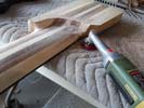
I am working on both the headstock and the neck/body transition because the neck thickness is a governing factor in both. Talking quite a lot of material off with the goal of minimizing the size of the overall body of the bass as much as possible.
|
|
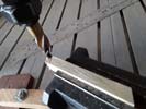
I have lot sof little operations to custom build this component. Right now bringing the blank to length with the appropriate angles at each end. Next I will set up to drill the 8 holes for the strings.
|
Left: I have the string retainer up on the cnc for some initial machining. I have a design that I think will work for this bass so moving ahead with this part while other tasks are going on! Right: Done with the machining of the end of the neck and I'm back onto carving and shaping that area to minimize the remaining material. |
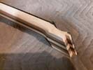
Se seat for the design of the string retainer is cut and I can now streamline the headstock area. Neck itself needs to come down a little bit in thickness too.
|
|
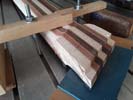
Doing a few machining operations to the back of the headstock.
|
Left: I am now machining a recess in the headstock for the string retainer. If I plan this right I will be done with the headstock work and can get the rest of the body finished up!. Right: I'm currently machining the string retainer hardware so that I can use that to correctly fit that into the back of the headstock nice and neatly! |
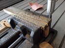
Rough machining the brass piece that will become the custom string retainer.
|
|
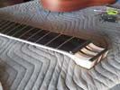
Nice to have the headstock finished to length - now looking at the cross-section to finalize that shape.
|
Left: Headstock has now been machined to length and I can now take a look at the thickness and the recess into which I will be housing the string retainer. Right: I now have the bass back up on the CNC so that I can cut and shape the back of the headstock and probably also create a recess into which I will house the string retainer. |
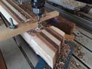
Doing a few machining operations to the back of the headstock.
|
|
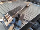
I will be machining the material off on the cnc as there are compound angles involved and I can do everything much more accurately with a nice clean finished surface on the CNC.
|
Left: Now that I have established the best place for string retainer I can machine off the remaining material from the end of the headstock that we no longer need. Right: Half way through machining the end of the headstock - being very careful to match the end of the string support piece. The will make the headstock area nice and short. |
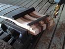
Busy cutting material off the end of the headstock to create a final surface.
|
|
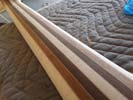
I'm removing material from the back of the neck to achieve the optimum thickness and comfort for playing!.
|
Left: More carving and sanding on the back of the neck on this bass. Need to retain strength but at the same time it has to be slim enough to play comfortably. Looking nice. Right: After a lot of thought & calculations I decided that the best way to keep headstock at absolute minimum length and still clamp strings was as shown. |
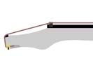
Moved string clamp to the back of the headstock which will help reduce overall length!.
|
|
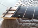
Took a lot of unwanted material off the headstock - probably another 3/8 inch coming off after I machine the slot for the string retainer!.
|
Left: The headstock has been shortened to assist with the design and installation of the string retainer. I will actually end up milling more material off when we are done with this feature. Right: The Roland pickup for the MIDI has to be a aligned with the bridge units at the best location and height for signal. I'm setting up the placementon the body. |
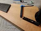
Roland pickup needs a certain linear relationship with the bridge saddles. I want to get all of the milling and sanding done so we can get this beast into finishing!.
|
|
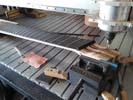
It will be good to get the mechanics of the string bending area and the string retainer done and out of the way!!!.
|
Left: This is a pretty delicate operation where I am machining the recess for the string support piece and when that's done I will also machine the final face of end of the headstock. Right: String retainer assembled onto the headstock and I am now deciding the best point to remove the remaining unwanted headstock material. |
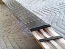
Next I will be cutting the headstock and adding a slot for the string retainer.
|
|
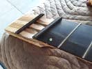
I'm going to make a suitabe recess for the string support bar on the left and then cut off the unwated length of headstock. I'll create a suitable recess for the string retainer.
|
Left: The nut is installed and I have filed down and cleaned up the two ends so that everything blends nicely. I'm now planning to shorten the headstock and get the string retainer set. Right: The string retainer should end up being fairly simple. I'm going as short as practical for string bending then adding string retainer behind headstock face. |
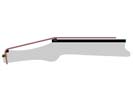
This arrangement should securely clamp the strings but distribute the tension and pressure between the string retainer and the carbon fiber radius to break the cornet for the strings...
|
|
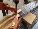
Clamping and gluing the nut retainer.
|
Left: Attaching the nut retainer piece to the end of the fingerboard. Once this is solidly glued in I will create a nut blank that will live in the recess this creates. Right: The nut blank has been rough cut and I will now have to shape it to fit perfectly and match the fingerboard radius. Will put the slots in when I get ready to add strings. |
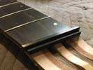
Nut blank rough cut and I will be getting this set into the instrument.
|
|
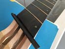
I now have the perfect assembly for the nut to live in. I'll trim this piece to seize and attach it and then cut the nut.
|
Left: I machined a piece of ebony so that it would provide the perfect fit for the nut material. I just have to trim this piece and glue it onto the existing neck assembly. Right: The end of the neck is now prepped for the nut which I am cutting out of a piece of solid carbon fiber I recently bought. Moving on now to the string retainer! |
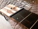
I have the nut base all prepared and I'm cutting a nut blank for the slot.
|
|
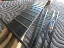
I wordered some special carbon material that will not only be more than hard enough for teh nut but also provide the viscosity to enable a little string bending.
|
Left: I am creating a nut assembly that will be strong enough to handle the string bending requirements and blend nicely with the neck and headstock of the instrument. Right: I put the instrument up on the CNC because I wanted to machine a very accurate end surface at the front edge of the fingerboard. |
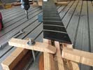
The goal here is to create a very accurate surface onto which I can add another piece of ebony. This additional piece will hold the actual nut material.
|
|
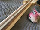
Generating the right thickness and profile for the back of the neck is a gradual process. I evening off the rough grinding I previously did, measuring the sizes and will be doing a phase two of the rough grinding to get the neck section thinner.
|
Left: Sanding the back of the neck - right now the goal is maintaining the relative sizes for the tapered thickness and making sure material is coming off evenly. I will be removing more thickness to get closer to final sizes. Right: Working on 3 things here - making a nut, creating the right string retainer and removing excess headstock material |
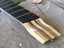
I will be installing a pretty solid nut assembly to handle any strain caused by string bending (mostly changes in tension) and I'm also planning to insert a string retainer that I will have to manufacture for the very end of the headstock area. I'll end up removing a couple of inches of that extra material!.
|
|

Fingerboard looks really good on the neck of the bass. This helps in a lot of levels, I can now grind more off back of the neck to get much closer to the finished neck profile. I will also get the top plate ready for installation and be looking at cavities for housing the electronics..
|
Left: Doing some creative programming so that I can get some cavities established for the assortment of electronic hardware that will have to exist inside the body of this bass. Right: I measured the physical sizes of all the electronic parts we plan to use inside the body. I'm laying them all out to achieve best arrangement. |

Fingerboard looks really good on the neck of the bass. This helps in a lot of levels, I can now grind more off back of the neck to get much closer to the finished neck profile. I will also get the top plate ready for installation and be looking at cavities for housing the electronics..
|
|
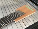
After gluing the fingerboard I had to do a good amount of glue cleanup. With that done I was able to re-fit the top plate around the neck heel. Next will be some final shaping around the body contour..
|
Left: Got the top plate re-fitted after the gluing of the fingerboard. I also trimmed the top plate close to the body size - still have to spindle sand to clean up corners and edges. Right: Did some sanding to resolve all the outer curves of the body shape. Some of the internal cavities will be cut from the top and some from the back! |
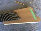
I brought the outer perimeter of the top in to match the body dimensions and also slightly rounded the upper horn corner - just needed the top and body to be close to finished width since the pockets for all the electronics are fairly critical in terms of available space.
|
|
Removed a lot of material to get down to a shape and thickness of the neck much closer to its finished dimensions.
|
Left: I have been grinding some of the extra material off the back of the neck to get a little closer to the finished neck profile for this instrument. Feels a lot lighter! Right: I'm looking at the set of electronic hardware so that I can correctly place all the required hardware inside the available space in the smaller instrument body. |
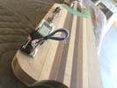
The electronics shown here are just those that relate to the Roland package. We have a MIDI output connector, a blend pot, a 3 way switch, two program scroll switches and also a standard output for the magnetic pickups only.
|
|
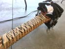
Always a fairly elaborate setup fpr gluing a finfgerboard on - have to have everything on hand and work fast before glue starts to bond.
|
Left: The fingerboard is now being glued on to the neck of the instrument. Once this has set I will clean off the squeezed out adhesive and clean everything up. Right: The fingerboard has been glued onto the neck and released from all of those rubber bands. I will be doing some basic cleanup along the edges to finish this all up. |
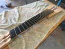
Fingerboard looks really good on the neck of the bass. This helps in a lot of levels, I can now grind more off back of the neck to get much closer to the finished neck profile. I will also get the top plate ready for installation and be looking at cavities for housing the electronics..
|
|
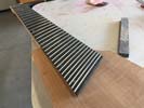
Ready to get the gluing done to attach the fingerboard..
|
Left: Neck has been positioned and pinned to prevent slippage and I am pretty much ready to get this fingerboard glued onto the neck. Both truss rods are set in place. Right: I have the clamping attachments and rubber bands ready and good to go - I just have to mix up the adhesive and get these parts glued together. |
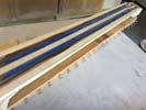
Takes a little setup time because you have to be sure to have all your materials right on hand before you start and mix the adhesive. There's no time for running around looking for stuff!.
|
|
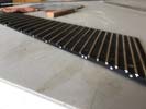
Side dots are all done and the look pretty good in there.
|
Left: I was able to get the side dot material implanted into all the side dot locations and I'm now cleaning up the surfaces and will be dressing the fret ends in preparation for attaching the fingerboard onto the bass. Right: Getting things ready to attach the fingerboard. Big step forward in having a complete instrument. Will look good! |
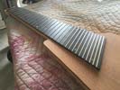
Now that side dots are taken care of I can get ready to attach this fingerboard to the rest of the instrument.
|
|
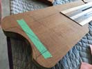
Further to my customer's preerences, I'm going to try to keep the geometry functional for the tuners but try to avoid causing the bottom bout area to look like a bump or knob!
|
Left: This is the current geometry of the back of the instrument. I was planning to leave the gentle curve at the end as is and recess the area marked in pencil to create finger clearance for tuners.. Right: Luminescent side dots are being installed along the upper edge of the fingerboard. Once this is done, fingerboard can go on the neck! |
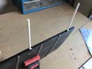
Testing installation of the side dot material. Once the adhesive is set I will cut them flush and sand flat and make sure they work. All being good I will go ahead and do the rest.
|
|
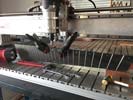
Drilling the side dots for the markers. Once this is done I will get them glued in and cleaned up.
|
Left: Now that the Luminlay material is on hand I can drill holes in the edge of the fingerboard at the right diameter to accept the side dot material. Right: OK - this is fairly impressive. I held one of these sticks up to a standard light for about a minute and then turned the light off. The resulting glow was surprisingly bright. |

The side dot material seems to be fairly responsive - better that I had expected actually!
|
|
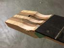
Relieving some of the material in teh string bending area. It may not only serve as a spave to depress (bend the tone of) the strings but it should also provide access to the two truss rod slots.
|
Left: Did a good amount of carving to further the string bending scenario on the headstock area. I need to test the overall length of this bass in a couple of my sample cases to make sure fit is good! Right: I received the Luminay rods from Japan and I will be installing this material per their instructions along the edge of the fingerboard! |
Although I haven't seen this product in action they seem to have had the best reviews from users out there who want a side dot that can be seen if light conditions are low. I'm hoping they work out..
|
|
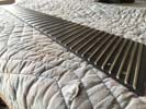
SI dresses all these frets down flush with the sides of the fingerboard so that the board is ready for machining of the side dots.
|
Left: I'm doing some prep to finalize positioning of the fingerboard as I will be attaching that to the neck of the bass pretty soon. Will look very impressive! Right: I spent a lot of time looking for side dots that "glow" based on exposure to ambient light. I was disappointed that many has poor reviews. Looks like Luminlay may work though. |

I looked at many options for glowing side dots - this company seemed to have the best engineered product.
|
|

First edge was carefully cut and looks good - now setting for second edge.
|
Left: Got the first body edge resolved and now setting up to cut the edge on the opposite side. This will also help me with the control cavities that need to be cut. Right: Both edges cut and the bass looks clean and balanced. Now I need to go back to some of the neck and headstock shaping and get that settled! |
Some corner rounding to do but sides are in the rright place and I will be working on other features around the tuner area.
|
|

Planning the nut geometry based on string bending requirements.
|
Left: More carving in the headstock area as I work my way in to a functional string bending mechanism. I'm doing the top first then will work on the back of the headstock. Right: I'm setting up the CNC so that I can cut the straight edges of the body profile on either side to a pretty much finished condition for sanding etc. |

The next 2 operations will give me finished egdes on teh upper and lower body. I will then finish the remaining profile from there..
|
|
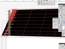
Doing calculations on string spacing, nut width and its relationship to the headstock angle.
|
Left: Working on the design of the nut. It has to not only space the strings at the correct depth but allow some flexibility for the string bending feature Right: Having looked carefully at options, the best way to achieve string spacing and the string bending action is to have a low viscosity nut and a support behind it. |

Carbon fiber rods cut and redy to go into the neck.
|
|

The fingerboard is now off the substrate and I'll be looking at side dot options and getting this attached to the neck!.
|
Left: I removed the fingerboard from the substrate mainly so that I can get the ends of the frets finished off to the edges of the fingerboard. Right: Doing a quick test of top plate and fingerboard relationships and marking out adjustments. Top plate is still a little bit oversize so need trimming. |

CI wanted to see how the top plate and fingerboard fit together as I have to set up bridge locations, do some marking out and revise the cut at the back to assure adequate tuner access.
|
|

The string ending option needs to have some space below the strings. I'm trying to create that space and keep the ends of the truss rods exposed and accessible.
|
Left: Some more shaping work going on at the headstock end. Working on the reduction of the material but still keeping in strong enough to sustain the string tension. Right: More body shaping happening right now, I'm combining the attached top plate so that I can evaluate the instrument as a whole. |
I will be adding a little undercut to guarantee finger access under the tuning knobs - just want to design that as elegantly as possible so it all blends with the shape of the body.
|
|

Slightly revised body contour at the back end based on how features fall in after the final placement of the fingerboard (which defines the various bridge positions) I may still have it slightly curved for aesthetic reasons.
|
Left: I found this photo which I wanted to post which shows the placement of tuner hardware and the slightly revised body contour which will be established for relief for the tuner adjustment knobs. Right: I was able to get all the frets dressed closer the edges of the fingerboard, this board looks awesome! |

Im in thr process of grinding the fret ends flush with the fingerboard edge. Right now they are flush with the substrate material so I am goin to separate the bopard from the MDF and finisg from there.
|
|

Frets now in the process of being installed. Using a LOT of fretwire for this one!.
|
Left: Got the first eight frets installed. I'm being very careful on these based on length of fret and making sure they are properly seated. Right: FInally got all the frets into this fingerboard - quite a big job. Happy with the results, now will start dressing the ends doen flush with the FB edges. |

Got all the frets into this fingerboard. Was careful to make sure each one was seated properly. Now need to dress down the oversize frets flush with the board!.
|
|

Fingerboard is now cleaned up, final sanded and ready for frets.
|
Left: I spent some time makng sure the surface of the board was nice and clean and even and I prepped it with 400 grit paper. Now ready for frets. Right: First operation with frets is to pre-bend the wire which I have now done. I'm getting started on cutting the frets and will now be able to get them installed. |

Frets now in the process of being installed. Using a LOT of fretwire for this one!.
|
|

This neck is now ready for its fingerboard. I'll get the frets installed first and then the board will be attached to the neck.
|
Left: The carbon fiber rods installed in the neck have now been sanded carefully down flush with the neck/fingerboard joint surface. Right: I have a special fret saw to do a final depth check on the fret slots before I start intstalling the frets themselves. Also gets rid of any dust or particles in the slots. |

Doing a final dressing job to the fret slots to make sure the depth is correct before the frets get installed.
|
|

Carbon fiber rods cut and redy to go into the neck.
|
Left: Doing some initial carving to set some basic sizes and dimensions for the headstock area and the string bending space. Should work out fine. Right: Time to get the frets installed into the fingerboard. This bass will be using an unusual amount of fretwire given the neck width and the number of frets! |

I bought sever 2ft lengths of fretwire for this fingerboard.
|
|

I will be sanding off some of the CF surface and glue to return joint face to a flat condition.
|
Left: Now that the CF rods are part of the neck assembly I have to clean up the top surface from any CF above the surface plus squeezed out adhesive etc. Right: The sanding process of leveling the CF is a but messy but it's important to return that joint surface to a perfectly flat condition for fingerboard. |

In the middle of working on the neck surface - messy job.
|
|

Gluing and clamping the carbon fiber rods into the neck.
|
Left: Carbon fiber rods are now being glued into the neck. These will provide a great deal of rigidity and stability to the neck structure. Right: I trimmed the substrate under the fingerboard down to the edges so that I would be able to get the best access for the installation of the frets. Should look awesome! |

Ready to install frets into the ebony fingerboard.
|
|

Nice to have the neck surface prepped. It will be ready for its fingerboard after the carbon firber work gets done.
|
Left: This is the neck surface with all its slots. I'm prepping the carbon fiber rod stock so that I can get the reinforcing rods installed. Right: Carbon fiber rods have been cut to length and are now ready to be glued into the slots in the neck. I will use a very strong epoxy to do this - end result is very strong! |

Carbon fiber rods cut and redy to go into the neck.
|
|

For each rod I have to cut three slots of different widths to fit the rods inside the neck correctly. Got the first one finished and will start on the second one.
|
Left: Just got back to this setup after doing some other work to clear my CNC table space. Got the first truss rod slot cut and successfully fitted the rod in there. Right: Both truss rod slots established and I am now in the process of cutting a couple more slots for carbon fiber rods for added strength and rigidity. |

Working on the two carbon fiber slots.
|
|
Readt to machine slots for truss rods and carbon fiber rods.
|
Left: I am setting the neck section up on the CNC machine so that I can cut the two truss rod slots and also the carbon fiber slots into the top joint surface. Right: Got the setup running after creating a special fixture to compensate for the angles of the two truss rods. Cutting the first slot right now. |

I'm getting started on cutting the first of the two truss rod slots.
|
|
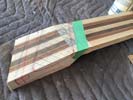
I removed a large amount of the headstock material based on calculations for string retainer, string bending and bridge allowances. I have a feeling it will end up shorter as we refine it.
|
Left: I cut the headstock back to about 1/4 longer than I think it will end up. Always good to play it safe but I think this will work. Right: I'm getting started on the carving of some of the headstock area so that I can get it closer to its finished shape. A new concept but I think it should end up working out fine! |
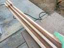
Working on back of neck and front of headstock.
|
|
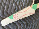
Didn't want to cut off any headstock real estate until I had seriously considered the mechanics of the entire headstock. We are trying to keep it as short as possible!.
|
Left: After some very careful consideration I came up with what I think to be the best bending length for the headstock plus string retainer. Right: I'm thinking of using 8 guitar bridge roller saddles as a bridge singe they are indvidual, spaced just about right, and can be built into a ebony of carbon fiber housing. |

This may be a very configurable solution for out nut. I buy two of these guitar bridges and employ the roller saddles in a vert sturdy ebony or carbon fiber housing.
|
|

All 30 fret slots have been cut into the fingerboard.
|
Left: Working on the sealer to allow me to create a perfectly flat surface on the ebony board. This will allow me to get the frets installed into the fingerboard. Right: Results are looking good on the inlay and I will be cleaning and leveling everything up so that the fingerboard surface is ready for frets! |

All 30 fret slots have been cut into the fingerboard.
|
|
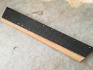
It was quite a bit of work to get a decent graduation in light and dark from my available shell since shell is inherently reflective. I was able to make the color graduation look pretty cool - I like it!
|
Left:Shell dots have been embedded into the fingerboard and I was able to get a nice graduated scale of light and dark in there. Right: I'm just about to set this body up so I can trim the sides down to the outseide edges of the green tape. That gives me some finished dimensions to let me establish the remainder. |

Getting ready to cut the two long body sides to finished size.
|
|

All 30 fret slots have been cut into the fingerboard.
|
Left: I'm installing the shell circles I cut into the fingerboard so that I can move on to the installation of the frets. Shell is color graduated between the two ends. Right: This is the fingerboard with the shell inlay laid out. Looks good so far - I now have to install and put a special filler on each one to seal them in. |
I sorted through all my dots that I cut from shell and geaduated them from dark to light.
|
|

I have set pre-sanded subtrate pieces into the inlay recesses. Shell will be next.
|
Left: Substrate pieces for inlay have been glued into fingerboard. These allow the shell to sit at an angle consistent with the top radius. Right: Evaluating the space required for the electronics. We have a very compact body and a lot of circuit boards and associated wiring to fit inside! |

I will be using every ounce of space in this small bodied bass for the electronics that will live inside.
|
|

The cross hatched area is what I am planning to employ for string bending. This will shorten the headstock quite a bit - might even go a little closer but won't know till I test.
|
Left: I did a little more carving at the headstock end of the neck to keep refining the geometry. I want it to be slim but need to also retain some strength! Right: The fingerboard has been surface cleaned and all the substrate pieces that will hold the shell inlay have been cut and prepared. |

Fingerboard has been prepared for the sjell inlay and when that's done it will get its frets!.
|
|

This is the working area for the pickup travel. It should give us a lot of tonal diversity. I just need to be sure that the pickup geometry and the recess in which it travels are geometrically aligned.
|
Left: I'm hoping to maximize the linear travel of the pickups within the recess between the neck and the bridge. Working on the geometry. Right: I was working on the spindle sander today bringing the back area closer to our drawing specs. There will be eight ABM string tuners in this area and I'm planning for that! |

Cleaning up the back area - I will need to recess the top a little for tuner access but it will look good.
|
|

I will be putting blue/grey shell inserts in the dot positions. If possible they will be graduated in color density from one end to the other so I am trying to cut them from various parts of the availale shell material to achieve that.
|
Left: These are some of the dot material blanks I recently cut on the laser. I'm going to be working on the inlay of the fingerboard. Right: I'm going to try a linear graduation of the dots with the brightest ones in the center of the fingerboard. They all reflect light in different ways but I think it'll work! |

I tried to lay out some of the shell material based on color density - I think they will all look great in the ebony fingerboard.
|
|

I'm machining both sides of the headstock closer to the necklines. When that's done on both sides I will work on the length of the headstock and the thickness..
|
Left: Some refinements being done on both the headstock and the body contour to bring them both into our drawing specifications. Right: This is the headstock after I removed some of the extra 'safety' material I left on a the early stages. I can now refine the shape a but to minimize the size. |

The headstock looks much better with the extra material removed. I now want to evaluate the length and see how short the headstock can be and still function with the string bender.
|
|

Roland MIDI package which I am measuring so that I can fit it into the body of the bass.
|
Left: This is the electronics package I have from Roland and I need to make sure I provide enough internal space to house the board and other controls. Right: I'm working on the geometry of the pickup that will be housed in the top recess. Once I have the pickup shape and the recess shape I can start cutting! |

Hoping to use as much of the available space between neck and bridges as possible.
|
|

This is the layout of the top of the body - I'm in the middle of planning where things go (tuners, pickup geometry, recesses and wiring slots).
|
Left: I have been plotting out all the features on the instrument that require space in the body in order to draw up the best (and largest) possible control cavity. Right: Planning on giving the pickup the maximum possible lateral travel inside their recess so plotting that out on my scale drawing helps a lot. |

Not a great deal of linear space to work with so I want to make the most of what we have. Doing some calculations to maixmize pickup travel..
|
|

More material off the back of the neck - now it acutally feels pretty comfortable for the left hand way up there.
|
Left: I have carved a good amount of the back of the neck now to provide access to the upper frets. This helps me calculate a few other aspects of the body. Right: I will have to harvest the material from the top plate to insert into the recess in which the pickup will travel. Designing pickup will help establish that. |

The space between the fingerboard and the ABM tuners is what I have to create a pocket for the sliding pickup design.
|
|

Some final perimeter shaping orior to establishing recesses for electronics/batteries etc..
|
Left: I'm using the drum sander to carefully blend some of the body edges and angles so that they are all the way down to template size and nice and smooth. Right: The neck-to-body angle is an important feature especially on an 8-string bass. I want to achieve as much access to the upper frets as possible. |

I will be carving quite a bit of material out of this joint to blend it nicely with the neck and body and achieve access for player's hand.
|
|

All 30 fret slots have been cut into the fingerboard.
|
Left: Back to work on the headstock area. I have left a good amount of spare material in this area- now it's time to design and modify for the string bending setup Right: I have done some drawing, marking out, grinding and shaping to get this headstock area a little smaller and closer to its final profile. |

This shot of the headstock shows lines I had drawn to indicate the material I could afford to remove from the headstock. From tests I have done 2 inches seems to be an ideal length for creating a string bend (plus or minus a little depending on string size) Also depends on how we design the string retainer.
|
|

I may be using some of these materials to guarantee a strong headstock area.
|
Left: I have carbon fiber solid bars and also carbon fiber woven fabric. I may use some of both to create a slim but strong headstock configuration. Right: Time to do some marking on the body blank to establish locations for hardware and the area I will have for pickup travel between fingerboard and bridge. |

Doing some calculations for layout of pickup and the space I will have to work with!.
|
|

All 30 fret slots have been cut into the fingerboard.
|
Left: I recently cut the fingerboard dot recesses on the CNC machine. These will look really nice when the shell material goes in. Right: I'm now drilling the holes in the upper edge of the fingerboard for the side dots. I will insert white dot material into these holes once they are established and sand them flush. |

Ready to drill all the side dot holes along the fingerboard.
|
|

This is a big surface area to prep and get flat. I want it to be very level and smooth before I machine for inlay.
|
Left: I'm busy sanding out the remaining machining marks on the top surface of the fingerboard so that I can get it set up for cutting the inlay hole pattern. Right: Trimming the fingerboard support down so that I can then go ahead and machine in all the holes for the side dots along the upper edge. |

I took all the support material off except the lower surface so that I can fixture the fingerboard in the CNC.
|
|

We'er going to be adding regular shell dots on the board. Color to be determined..
|
Left: I will be adding some basic dot inlay into the fingerboard. I'm setting that up on the computer so that I can get the recesses cut out on the CNC. Right: I revised the dot layout because the fingerboard based on the width of the board. This layout makes it easier for the player's line of sight. |

Slightly revised dot pattern.
|
|

Fingerboard radiused and I'm now cutting the fret slots.
|
Left: I was able to get everything settled on geometry and also ran the compound radius to the point where I am happy with the end result. Now cutting fret slots. Right: The fret slot work in the fingerboard has been completed and I will probably move on next to getting the side dots established. |

All 30 fret slots have been cut into the fingerboard.
|
|

Some tricky operations where I am checking board geomethry against the geometry of the upcoming fret slots to make sure everything works together.
|
Left: I am taking this couple of operations very carefully because I am not only establishing the final width of the board but the finished angles. Right: I'm now cutting the compound radius on the top of the board. It's a large area so takes a bit longer to do than a regular fingerboard! Also requires a few cuts. |

Generating the compound radius on the top of the fingerboard.
|
|

GDoing some double checking on neck geometry to make sure what I cut is mathematically perfect.
|
Left: The geometry of this fingerboard is quite complex so I am double checking fret slot artwork before cutting the fret slots. Right: Startng by establishing the outer perimeter of the board. The blank I cut is about 2/16 oversize. Once I'm happy with shape I'll test against fretslots then cut compound radius. |

Cutting some of the meat off the fingerboard to establish outer perimeter.
|
|

Looking pretty good with the top plate fitted!.
|
(9/12/16) Left: This is the bass with the top plate fitted and some of the perimeter cleaned up to fit the body contour. This helps me plan for pickups and wiring channels. (9/24/16) Right: Fingerboard is now up on the CNC and we are going to get quite a lot of work done on its shape and profile in the next few machining operations! |

Fingerboard up on CNC for a bunch of machining work!.
|
|

Testing the program but cutting and fitting a scrap piece of wood. It was very close so I made the appropriate adjustments.
|
Left: In order to guarantee the best possible fit between top plate and the end of the neck I am testing the program on a spare piece of material. Right: My test piece fit very close, so after a couple of minor adjustments I felt it was safe enough to proceed with the actual top plate. Looks like it will work out fine! |

Got the neck relief cut out of the top plate.
|
|

Getting set up to machine nack relief in top plate.
|
I am now getting everything set up to cut out the neck heel angle from the bookmatched top plate. That will allow me to get the top plate properly fitted which will in turn allow me to establish fixed locations for the bridge hardware and the pickup placement. Once these are marked out I can cut wiring channels in the top of the body which is much easier than thrying to drill holes inside a completed instrument body! More pics to follow! |
|

Top plate glued and sanded.
|
This is the top plate after gluing was completed and the top surface was then sanded to remove excess glue etc. It has a really nice grain running along and across it and I am very confident it will look beautiful on the finished instrument. I now need to get back to my scale drawing and write a program that will allow me to cut out the joint area at the front of the top plate that will allow it to fit onto the instrument around the end of the neck, |
|

Gluing the top plates together.
|
In this photo the two halves of the bookmatched top plate are being glued together. I'm clamping them together laterally and at the same time clamping the two pieces solidly onto a non-stick surface so that I can guarantee flatnedd when we are done. When this is complete I will then clean up the glued piece and get it ready to be machined to fit the end of the neck profile on the body. I save some of this material for the headstock area too! |
|

Machining a very accurate joint face for the bookmatched top.
|
I got the two top plates up on the CNC so that I could cut the best possible clean and square joint face across both pieces. This will allow me to create a very clean joint between the bookmatched top halves. Next task will be to get these plates glued together so that we have one complete top. Before the top goes on I will map out the cavity space within the body profile and qalso cut thechannels that will house the internal wiring under the top. |
|

Grinding and sanding the back of the instrument to refine the neck contour.
|
I have been removing material from the back of the bass to transform the instrument from a set of glued laminates to something in the shape of a bass guitar neck. Initially this involved removing a whole lot of excess material which has now been done. I'm now working on the profile of the back of the neck and the two areas where it meets the headstock and the body. In those areas the transition geometry can be fairly complex. |
|

Figured Sapele top plates ready for veneer and machining.
|
The two Sapele top plate halves are in the vaccuum press right now where I am adding some decorative veneers to make the assembly look even more impressive! It's always best to do this veneer application before I bookmatch the two halves together. As soon as this is done I will cut the joint faces on the CNC and then carefully glue the two pieces together to make one complete top. I'll probably use the same saple on the headstock area. |
|

Figures Sapele top plates ready for veneer and machining.
|
This is the figured sapele material I am using for the top plate. I really like it for two reasons: One is that it will look very beautiful on the finished instrument in terms of color and grain, theother is that it matches two of the laminates I used in the core section perfectly! The material has been cut a little oversize so that I have room to machine a very accurate joint surface on each and bookmatch the two pieces together. It will look really good! |
|

Body has been trimmed and will now get some final shaping.
|
This is the bass body now that I have trimmed it to size and cleaned up around all the edges. I needed to do this so that I can plan for a couple of things. One will be the cutting of the top plate pieces and the other is to plan space in the body for the batteries and the electronic controls including the pots, wiring, switches and circuit boards that will be involved. I believe there is enough space for me to create a suitable cavity for all this! |
|

Body has been trimmed and will now get some final shaping.
|
With the back section removed I needed to take a look at the body profile and update it to suit out plans. I re-drew the template to reflect some of the body shape discussions we had and I now need to do some work around the profile to bring the edges to final sizes. Part of this is because I also want to get the fingerboard completed and in turn fitted onto the neck. That way we will have a better feel for the whole instrument. Much lighter now! |
|

Establishing some physical sizes before cutting the radius at the back of the body.
|
I'm now doing some calculations based on scale lengths to establish how to cut the back radius on the body. The curved area at the end can be easily enough removed but I want to be sure the ends of the tuner knobs are acessible and have enough space below each of them for the player's fingers to easily adjust. I'll probably scallop out some of the Sapele below each tuner to achieve that without breaking the continuity of the top plate surface. |
|

Some really beautiful figured sapele for the top.
|
I have some really impressive looking figured sapele which I am going to use for the top plate of this unique bass. I have had this material for a while in the hope that an instrument would happen whose body was small enough to fit the material. In this case we have a good fit and I know the bass will look really impressive with this very attractive top. I have it sanded already so I will rough cut it and get it bookmatched together. |
|

Machining on body complete for the moment. Need to now plan for tuner locations and refining body shape closer to finished size.
|
This is the assembled bass so far. I cleaned up and leveled the top surface so that it is ready for the top plate. My next move will be to do some shaping around the body to bring the profile closer to out template. Right now everything is oversize for safety but at this point I can cut and shape much closer to finished size. I will also plot out all the tuner locations so that I can cut out the relief at the back with confidence! |
|

The top surface of the bass has now been machined.
|
After having established the contour of the end of the neck I then had to machine off the extra body material from the top to blend with the depth of cut around the neck. This newly generated surface will be the joint face for the top material. I had to calculate the correct depth for both operations based on the anticipated thickness of the top and the height of the tuner/bridge assemblies. I expect everything to work out fine! |
|

I have now established the 30th fret geometry on the end of the neck.
|
I have done some important machining on the bass body to define the end of the fingerboard area. This establishes where the fingerboard will be attached and all the features from that point back to the tuners. I machined the end of the neck to exactly match the profile of the neck at the 30th fret position. This allows me to machine the fingerboard so that there will be a small overhang to the virtual 31st fret. Now I need to machine the rest of the top. |
|

Doing the math on the fingerboard so that I can be sure subsequent machining operations work out correctly!
|
I had to sit down and go through my vector file plot to make sure I had good reliable dimensions for the fingerboard. This is defined by the two scale lengths. the offset between the scale lengths and the resulting fret positions. The actual fingerboard dimensions have significant impact on how I machine the top of the body so that all the part geometries end up fitting correctly together. The photo show the two scale lengths and the 30 fret positions. |
|

Body shape revised and updated. I can now get the body closer to finished shape
|
This is the body end of the bass with the two body halves attached and the outer shape of the bass rough sawn. This obviously helps a lot in reducing the bulk and weight of the roughed out body. Next I have to do some machining to establish finished thickness. The bass now looks a lot more like our original concept and I will be marking out and cutting down to the final body profile shape very soon. I will also need to plan out cavities to make sure I have room for all the electronic hardware. |
|

Body shape revised and updated. I can now get the body closer to finished shape
|
The body shape has been established based on my customer's preferences and the original drawings we had for the 6-string version of this bass. I needed to get them worked out so that I could cut out some of the excess material from the body blank I recently glued together. I'm going to be doing some rough sawing to bring the body profile relatively close to these drawing dimensions so we csn see how things work out. |
|

Checking vector layout before I commit to machining fingerboard geometry.
|
I have just done some machining to the body of the bass. The objective here was to firstly machine a nice flat consistent surface on the back of the body and then, using that surface to locate on, macine the top surface of the body to not only create a body thickness but to provide a nice flat face onto which we will attach the top plate. I will also need to machine some wiring channels too but with such a compact body these will be fairly minor. |
|

The headstock area which will have a string bending feature added to it.
|
This is a view of the headstock showing the material I have allowed for the string bending mechanism. Obviously there is a good amount of extra material on this area right now but I am drawing out a cross-section for the string bender that will allow me to start shaping this headstock with the geometry of that feature in mind. That will allow me to get the fingerboard fitted since the multiscale layout creates an angle at the headstock end. |
|

Removing extra material from meck and headstock areas so I can move things forward.
|
I spent some time today removing excess material from the back and sides of the neck so that I can proceed with other work relating to the headstock and the string bending system. I cleaned up both sides of the neck and cut back the area behind the string retaier/string bender area. I will be creating a final template for the actual body shape soon and will use that to cut the body profile. The wood laminates are going to look great!!! |
|

Checking vector layout before I commit to machining fingerboard geometry.
|
I am working on making sure the geometry for this bass is correctly established. My original calculations were for a 6-string bass so I do have to adjust some of the parameters to allow for the wider fingerboard and the resulting changes in fret placement geometry. I'm going through the vector drawing to double check fret positions before I go ahead and cut into that big piece of ebony fingerboard that I would have a hard time replacing!!! |
|

Clamping the first of the two body half blanks onto the core.
|
This is the first of the two body halves being attached to the core section of the instrument. I typically clamp the assembly in two directions. Firstly laterally to squeeze the two joint faces firmly together but also they are being collectively clamped down onto a flat non-stick surface so that I can guarantee that the back of the core and the faces of the side pieces will be flush. This saves me a lot of cleanup work. |
|

Machining and sanding the body halves prior to assembly.
|
I machined the two side pieces down a little bit and then ran them both through the drum sander to give me nice clean and parallel surfaces. I am now ready to attach them to the center core of the instrument. When I have them both glued on I will use a template for the body profile and at least get the body shape roughed out then finished pretty close to the final size and shape. That will allow me to cut out the cavities. |
|

Cutting pieces for the upper and lower body halves.
|
I made a body shape template that I can use when body halves are attached, and in the meantime cut out a couple of blanks that will very soon become the upper and lower body halves. I want to get these attached so that I can get some of the other work done - specifically the cavity area in which the sliding pickup assembly will live. I'll get these cut and fitted and that will definitely get usin a better place to plan the mechanics! |
|

Ebony fingerboard now attached to MDF board and ready to go on CNC for several machining operations.
|
While I'm getting things ready to go on the CNC I secured the fingerboard to a subtsrate of MDF which will allow me to securely attach it to the machine table and keep it rigid during machining, side bot installation and even the installation of the frets. It's a beautiful piece of ebony and will look great on the finished instrument. Next operation is cutting the perimeter followed by generating the compound radius on the top. |
|

Gaboon Ebony for the fingerboard - rough cut and ready for machining.
|
This is the fingerboard blank for this bass. It is Gaboon Ebony which is becoming very expensive and really hard to find at the physical size required for an 8-string bass! I was quite lucky to be able to get hold of this piece. Right now it is drum sanded flat on both sides but about 1/8" oversize all round. When this board goes on the cnc I will cut to finished size and I will be putting 30 fret slots into it! Should look pretty impressive! |
|

Gluing on decorative veneer on the sides of the core section.
|
In order to prepare for the body halves I am gluing some dark veneer onto the sides of the core section so that we continue the pinstriped theme through the bass. I'll do this to both machined sides of the core and it will be ready for further gluing. I want to get the body on so that I can do some of the final machining and also to get ready to create a top plate for the instrument. |
|

Some maple from which I can create the sides of the body.
|
I am planning to add the sides, or extensions to the body and will probably use this curly maple which has a nice figure and will take on the color very well also. The body section isn't that large but now is a good time to get it established because I have to make sure the control cavities are large anough for electronics and also that I have enough internal room to add the mechanism for a sliding pickup. Should be interesting! |
|

Machined the edges of the core for the body half joints.
|
I just ran this core section on one of machines to generate accurate square machined sides on both sides of the assembly. This gives me precise joint faces and allows me to get the sides of the instrument prepped for the addition of the body halves. I will also be setting this core up on the cmc to cut the truss rod and carbon fiber slots. I just want to map out the fingerboard geometry first so that everything falls into place! |
|

Proposed Roland GK-3B system.
|
Jumping ahead in the timeline a little - just to say that the Roland GK-3B internal pickup kit arrived. I can now look at the net space required in the body cavity and make sure that there is adequate cavity space in the body of the instrument to comfortable house this unit and some of the other electronic gadgets that will be in there too. This unit was pretty hard to acquire and I'm happy it's now on hand! |
|

Machining back surface of body.
|
A lot of the machining work has been done to the core section of the bass, now I have to machine the back parallel to the front face (which has neck angle compensation) and clean this surface up so that it's ready to have the instrument sides attached. Once this surface is machined it becomes the final back surface. I will then machine the two sides in preparation for attaching the side pieces. Fingerboard also under way. |
|

Proposed Roland GK-3B system.
|
I'm planning to put this system into the bass. It is a Roland GK-3B kit designed to be installed internally. This will provide a MIDI output signal for six of the eight strings on the bass. The Graph Tech system is expected to feed the lower string signals. We may have to do some experimenting but hopefully these two systems will co-operate together and give us the output we want! This bass will create a lot if interesting sound. |
|

Neck-to-body angle has been machined.
|
In this photo you can see the body end of the instrument where I have just finished machining the angle of the body relative to the top surface of the neck area. This surface is critical because it governs the relationship in height between the fingerboard, strings and bridge. It is also further complicated by the fact that this is a multi-scale instrument and many other geometric factors are involved. |
|

Cleaned up the headstock angle area. Will need further machining but good to set a datum surface.
|
I have machined a nice flat surface on top of this blank so that we have a good reference surface to work from. It will also be the joint surface for the fingerboard when it goes on. I then cleaned up the headstock angle. This gives me a co-planar reference surface which helps in my future calculations. Because we have a multi scale instrument this area will need firther more complicated machining but right now it's cleaned up! |
|

Core is set up on machine for a few operations.
|
The core section of the bass has now been set up on the CNC for some machining operations where I will cut the top surface (onto which the fingerboard will be attached), I will machine the "headstock" angle that will become part of our string bender assembly, and I will machine the neck-to-body angle based on the scale lengths and the bridge geometry. I may also include the truss rod slots and the carbon fiber slots. |
|

Core laminates complete - now ready for machining.
|
We now have a complete core to our bass and my next task is to find an opportunity to get this assembly up on the CNC machine so that I can start cutting some of the reference surfaces. Following that I will want to machine the sides and prep them for the extension pieces that I need to add to create the body section. I will need two truss rods in this nack based on the width so it's good that it feels lightweight! |
|

Six out of seven laminates now glued together.
|
This is the core section after the 6th of 7 laminates have been glued together. I'm ready to get the last one on so that I have a complete core to work with and this will then let me do some important machining operations which will establish a lot of the instrument geometry. For an 8-string neck this assembly doesn't feel too heavy which is a good sign. Once all the extra material is removed it should be relatively lightwaight for its size. |
|

Getting the last few veneers onto the core section.
|
Before I glue the last two Maple outer laminates onto the core I have to add a contrasting veneer of maple to the Sapele. I will also be adding a veneer of Lavoa to the outer maple laminates. Once those are on i will be able to get the last two laminates to the outsides and the core section will then be completely assembled. Following that there will be a number of machining operations on the CNC. |
|

This is the core section with first laminates glued together.
|
I now have five of the seven nack laminates veneered and glued together. The core section looks really good so far and I am even further encouraged that our choices of wood are yielding what promises to be a pretty lightweight and resonant core component even for an 8-string bass. I now have some more veneering to do and then I will get the last two pieces attached to complete this part of the instrument. |
|

Gluing 3 of 7 right now - pretty happy with it all so far.
|
More laminate gluing going on. Gluing these laminates, especially when dealing with more than one instrument, uses all my clamps and much of my bench space - not to mention the time waiting for glue to cure. I just leep swapping things out - gluing the next thing as soon as I uncl3mp the last! We're definitely getting there and we'll have a beauitiful and rigid neck assembly very soon. Looking forward to that! |
|

Starting to glue the individual veneered core components together.
|
This photo may look like some of the preceding ones but it is significant in the sense that it shows the first two of the seven core laminates being glued together. This process will continue with one laminate at a time until we have the complete 7-piece core assembled and ready for ongoing machining operations. It's always nice to get past the preparation stages and get started on the actual assembly! More to come. |
|

Gluing veneer onto Wenge laminate.
|
Applying the veneers can be a little time consuming but always worth the effort on the finished instrument. We have seven different laminates to treat but the trick is to just keep doing one after the other while you are busy with other workshop duties. In this photo we are applying maple to one of the wenge laminates. My goal is to get enough of them veneered so that I can start gluing things together. |
|

2nd side of center laminate getting its veneer applied.
|
While I am busy sanding and prepping the other laminates I am also gluing the lavoa veneer to he second side of the center core laminate. This gets things started on the core assembly and that in turn will allow me to get the body components cut and shaped so that we have the whole profile and shape of this bass assembled. Once that's done I'll be able to cut cavities and get to work on the fingerboard work. |
|

Gluing veneer onto the center laminate.
|
I am now gluing veneer onto the center laminate of the core assembly. The material of the laminate is maple so i am gluing a darker Lavoa veneer onto both sides to create a contrast. Once I have both sides veneered I will be able to start assembling the core structure fron the center out. Should look really nice when it all goes together. The darker laminates will have lighter (Maple) veneer applied to them. |
|

The 7 laminates together, ready for veneers.
|
These are the component laminates that will be assembled to create the core of this unique bass. I have been machining the individual laminates to the correct tapers and I'm now working with veneers to prepare the joint faces for assembly.Since this is now an 8-string bass I had to use a littl;e more material to yield the correct width but so far all is looking good and we are moving ahead. |
|

Gluing veneer onto the laminates already cut.
|
In this photo I am gluing veneer to one of the sides of the Sapele laminates. I will have to do this to both sides of each tapered laminate but the end result will really complement the assembled end result. I need a lot of beneer for a 7-piece neck assembly! Once my veneers are on the laminates I can start gluing the laminates togethe. At that point we will start to see what all these beautiful woods look like together! |
|

Two Wenge laminates ready to be machined to tapers.
|
The two Wenge laminates have now been sanded flat and are ready to go on my CNC machine to be milled down to the correct taper sizes. I have bolted these two matching pieces onto the machine and set the taper so I'm now ready to start cutting. Once these are done I will have a center piece of Maple to machine. I have my veneers ready so as soon as these are cut I will be gluing them up ready for assembly! |
|

Cutting the two Sapele laminates so that I can start the assembly.
|
I am in the process of machining the two Sapele laminates to their designated tapers. While I was busy working on this I thought I would take a photo so that I could update this page. I'm almost done with these two laminates and as soon as I get these off the machine I will get the center Maple laminate machined. That will give me enough material to assemble the first three laminates of the core section of the bass! |
|

Maple and Wenge laminates ready for machining.
|
Aside from the two laminates that are being machined for tapers, these are the other laminates that will be going together to make up this 8-string neck and core for the bass. A 7-piece neck is very strong and the Maple and Wenge will work great together as a formula. The sapele right between the two in color and density so it will definitely add a lot to the recipe too in tems of sound and aesthetics. |
|

Laminates are now set up on CNC for machining.
|
I took the first two (Sapele) laminates and got then set up and dialed in for the machining process that will create the tapered laminates. I will follow up with the other parts of the neck but these two will allow me to get started on the basic assembly work. I have a Maple laminate to run through the system too, followed by two wenge and two more maple for the outsides. This 7-piece neck will look good! |
|

Drum sanding the Sapele laminates - messy job but they look nice!.
|
I like to do my sanding outside even although I use an extractor when necessary. It's still a dirt dusty job but somebody has to do it and it's usually me. Right now I am sanding the two Sapele laminates. I will clean up both sides so that they are flat and parallel and they will then be ready to go on the CNC machine where I will set up to have them cut to the correct amout of taper. Want to get this neck built! |
|

Sapele laminates cut, now to get them sanded and tapered.
|
We now have our two Sapele laminates for the core section of the bass. As with the other laminates I will be sanding them on teh drum sander to give them good location faces. Then they will go up on the cnc machine in paire so that I can cut them to their tapered profiles. We will then be able to see the core of this instrument come together and I can start machining. Looking forward to seeing things take shape on this project. |
|

ready to cut two more laminates - this time some really nice Shedua.
|
Since our 8-string will have a wider neck I'm adding a good sized set of Sapele laminated to the core section of the instrument. It will be a 7-piece assembly and I'm currently working out the respective taper sizes so that we have a great solid center core for our instrument. The Shapele is a very good compliment to the Maple and Wenge and we will yield a bvery strong and resonant assembly from these pieces. |
|

Two of the maple laminates have been cut.
|
Now that we are looking at the linkelihood of an 8-string instrument I have had to reconsider how the construction of the neck laminates will combine. I think the formula of three maple laminates supported by wenge and shedua laminates will not only yield a good sound but will look pretty spectacular on the back of the instrument. I will do my typical; decorative veneer pinstriping which will further enhance the effect! |
|

Neck laminates and the Roland Synth package.
|
Two things illustrated here. On the left is my anticipated laminate construction for the 8-piece neck. I want to keep the neck mainly Maple and use Wenge and Sapele as a means to keep the tone warm and growly! We may stain the combo atrans brown. The picture also includes a photo of the Roland GK-3B kit which will allow me to install all the functions of a standard GK-3B synthesiser inside the body of the machine! |
|

Revised template allowed me to cut the first core laminate and test it out.
|
As a result of my calculations on the computer I was able to create the optimum profile template for this bass, whether it ends up being 6-string or 8-string. The template allows for the slightly increased scale length difference for 8-string and also has material allowance for the string bending system to the top of the neck. I used the template to cut the first piece of Wenge so that I could verify everything. Looks goo so far. |
|

Right in the middle of recalculating some of the dimensions if we change to 8-strings.
|
Some changes to this build are going on right now and I am doing a couple of revisions to the vector artwork. We are likely to change the instrument from a 6 to and 8 string. That in itself creates quite a few engineering modifications which I am working on. The other consideration is whether a string bending option is still realistic if we upgrade to 8-strings. We're also looking at the electronic implications! |
|

Looking at a method to allow the player to manually bend the strings.
|
We have a lot of technical challenges with this bass so careful planning is required in the early stages. It is very likely that this will end up being an 8-string bass so I am doint some alterations to out master plan to bring that together. At the same time - we're planning to incorporate a string bending system similar to the one shown where the player can manually change the string pitch. I'm allowing extra material for that too. |
|

Marking out template dimensions on some of the maple.
|
Since this project has some quite uniqe features I have had to create a new template before I cut out the blanks that will go together to create the core of the instrument. I had to allow a few extra inches and some additional material due to the space on the headstock where I will be incorporating a string bender system. Basically it is a few inches of free space between the nut and string retainers where the player can apply bending pressure. |
|

Curly Maple destined for neck laminates.
|
I bought some very nice curly maple to use for the rest of the core of this instrument. I will get all the pieces for the core cut out and sanded both sides so that they are ready to be machined to their specific tapered dimensions.This will end up being a strong and resonant assembly. Maple and wenge are a popular combination for good tone. I will probably use the wenge for the outer edges and have contrsting maple strips. |
|

Wenge planks which will soon become neck components.
|
Looks like we will have Wenge and Maple on the menu for the core section of this bass. This is about the safest choice in my opinion. The characteristics of these two woods work well together and always produce a dynamic sounding resonant instrument. I will now be cutting blanks out so that they can be sanded and prepped for machining to their respective tapers. Looking forward to getting the core section established! |

